
4 Local Web Interface
4.1 Overview
The Micro Web interface (Rune) is accessed on site via a laptop or a smartphone using the LAN. The interface provides the user with an overview of the status of the Micro Modular system and active alarms. It also offers possibilities to configure the system, update controller softwares and download backup data.
Rune runs on port 3000 and requires authentication to access all pages except the login screen.
From the front page, which displays an overview of the most important system information, tabs with more detailed information about various system parts are accessed. An example of the view on the Rune front page is shown in Section 4.3. Click the labels on the menu bar to access the detailed information sections and to configure the system.
4.2 Authentication
4.2.1 User Levels
Rune supports two user levels, 'Operator' and 'Admin'. Each user requires a unique user name and a password. Default passwords are provided by Clear Blue Technologies. Passwords may only be changed by an 'Admin' user.
| User level | Access |
|---|---|
| Operator | View data and alarms (read only). |
| Admin | View data and alarms. Configure the system. Update system software and download backup data. |
4.2.2 Password Change
Available from the user profile dropdown. Requirements:
Minimum 8 characters
4.3 Dashboard
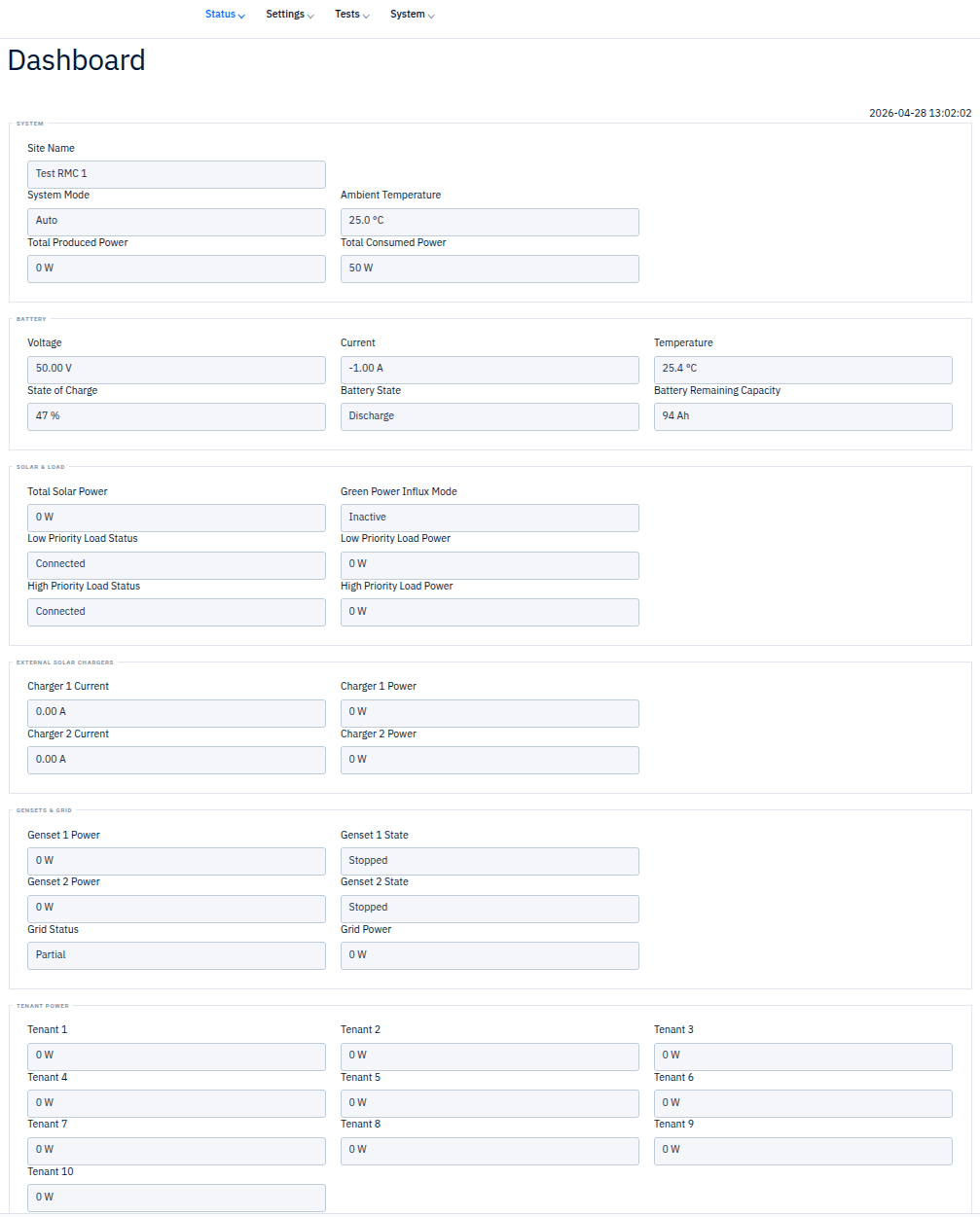
The dashboard displays real-time system data, updated every 1 second.
System
| Field | Unit | Description |
|---|---|---|
| Site Name | — | Configured site name |
| System Mode | — | Current operating mode |
| Ambient Temperature | °C | Outside battery cabinet temperature |
| Total Produced Power | W | Total power being produced |
| Total Consumed Power | W | Total power being consumed |
| Date | YYYY-MM-DD | Current local date |
| Time | HH:MM:SS | Current local time |
Battery
| Field | Unit | Description |
|---|---|---|
| Voltage | V | Present battery voltage |
| Current | A | Battery charge/discharge current |
| Temperature | °C | Battery cabinet temperature |
| State of Charge | % | 0% = empty, 100% = fully charged |
| Battery State | — | Current battery state |
| Remaining Capacity | Ah | Remaining battery capacity |
Solar & Load
| Field | Unit | Description |
|---|---|---|
| Total Solar Power | W | Total solar production |
| Green Power Influx Mode | — | Green Power mode status |
| Low Priority Load Status | — | Connection status |
| Low Priority Load Power | W | Consumed power |
| High Priority Load Status | — | Connection status |
| High Priority Load Power | W | Consumed power |
External Solar Chargers
| Field | Unit | Description |
|---|---|---|
| Charger 1 Current | A | External charger 1 output current |
| Charger 1 Power | W | External charger 1 output power |
| Charger 2 Current | A | External charger 2 output current |
| Charger 2 Power | W | External charger 2 output power |
Gensets & Grid
| Field | Unit | Description |
|---|---|---|
| Genset 1 Power | W | Genset 1 produced power |
| Genset 1 State | — | Genset 1 operational state |
| Genset 2 Power | W | Genset 2 produced power |
| Genset 2 State | — | Genset 2 operational state |
| Grid Status | — | Grid connection status |
| Grid Power | W | Power drawn from grid |
Tenant Power
Power readings for up to 10 individually measured tenants (Tenant 1–10), displayed in Watts.
4.4 Battery Information
The Battery page provides detailed battery monitoring and control.
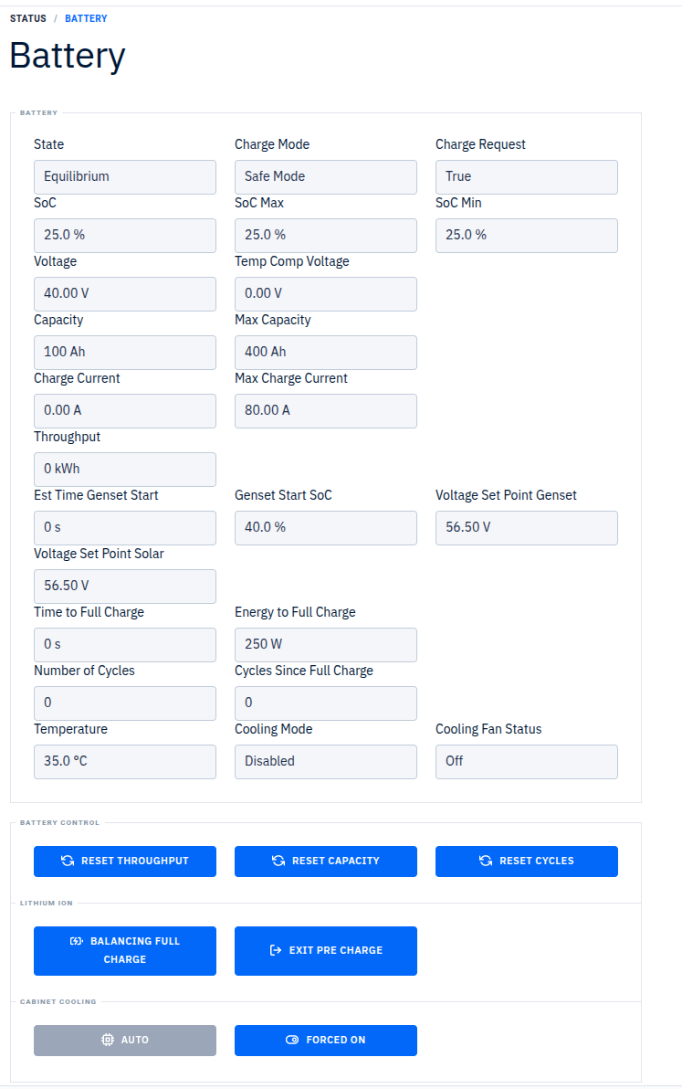
Status Fields
| Field | Unit | Description |
|---|---|---|
| State | — | Precharge / Discharge / Charge / Absorb / Equalized / Equilibrium / Fully charged |
| Charge Mode | — | Normal charge / Full charge / Extended Full Charge / Balancing Full Charge / Safe Mode / Ramp Up / Synchronize |
| Charge Request | — | Not active / Active |
| SoC | % | State of Charge |
| SoC Max | % | Maximum SoC across BMUs |
| SoC Min | % | Minimum SoC across BMUs |
| Voltage | V | Present battery voltage |
| Temp Comp Voltage | V | Temperature-compensated voltage |
| Capacity | Ah | Current capacity |
| Max Capacity | Ah | Maximum capacity |
| Charge Current | A | Current charge/discharge current (negative = discharge) |
| Max Charge Current | A | Maximum allowed charge current |
| Throughput | kWh | Total energy throughput |
| Est Time Genset Start | — | Estimated time until genset start |
| Genset Start SoC | % | SoC level that triggers genset start |
| Voltage Set Point Genset | V | Target voltage when genset is charging |
| Voltage Set Point Solar | V | Target voltage when solar is charging |
| Time to Full Charge | — | Estimated time remaining |
| Energy to Full Charge | kWh | Estimated energy remaining |
| Number of Cycles | — | Total charge cycles |
| Cycles Since Full Charge | — | Cycles since last full charge |
| Temperature | °C | Battery temperature |
| Cooling Mode | — | Cabinet cooling mode |
| Cooling Fan Status | — | Off / On / Forced On / Fall back |
Battery Controls
| Button | Condition | Description |
|---|---|---|
| Reset Throughput | Always | Reset total energy throughput counter |
| Reset Capacity | Always | Reset capacity measurement |
| Reset Cycles | Always | Reset charge cycle counter |
| Full Charge | Lead-Acid only | Trigger a full charge cycle |
| Extended Full Charge | Lead-Acid only | Trigger an extended full charge cycle |
| Balancing Full Charge | Lithium-Ion only | Trigger a balancing full charge cycle |
| Exit Pre Charge | Lithium-Ion only | Exit precharge state |
| Auto (Cooling) | Cabinet cooling configured | Set cooling fan to automatic |
| Forced On (Cooling) | Cabinet cooling configured | Force cooling fan on |
BMU Data (Battery Management Units)
For each installed BMU (up to 16):
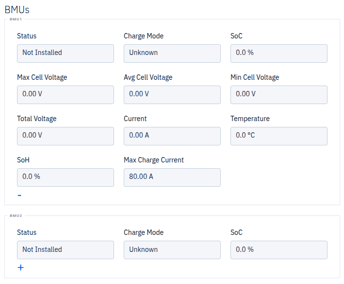
| Field | Unit | Description |
|---|---|---|
| Status | — | Invalid / Not installed / No communication / Operational / Not Operational |
| Charge Mode | — | Charge or discharge |
| SoC | % | State of Charge |
| Max Cell Voltage | V | Maximum cell voltage |
| Avg Cell Voltage | V | Average cell voltage |
| Min Cell Voltage | V | Minimum cell voltage |
| Total Voltage | V | Total module voltage |
| Current | A | Module current |
| Temperature | °C | Module temperature |
| SoH | % | State of Health |
| Max Charge Current | A | Maximum charge current for module |
4.5 Genset Information
The system supports up to two gensets. Each has a dedicated page (Genset 1, Genset 2) with identical layouts.
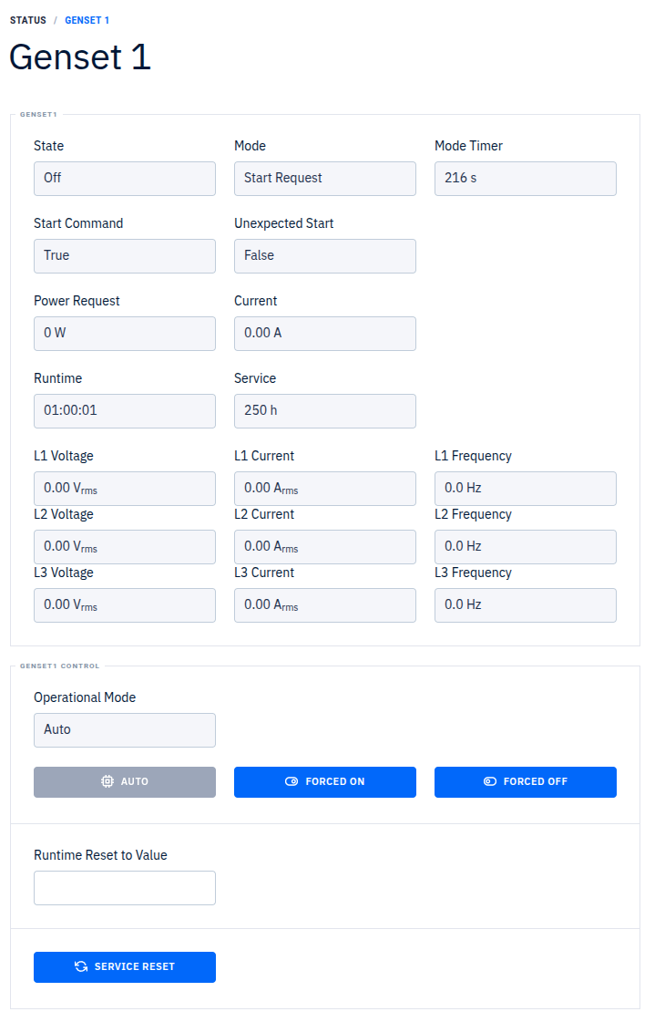
Status Fields
| Field | Unit | Description |
|---|---|---|
| State | — | Stopped / Running |
| Mode | — | Ready / Start Request / Warm Up / Ramp Up / Run / Ramp Down / Cool Down / Off / Exercise Run |
| Mode Timer | — | Duration in current mode or countdown |
| Start Command | — | Whether start command is active |
| Unexpected Start | Yes/No | Running without active start command |
| Power Request | W | Requested power |
| Current | A | Produced current |
| Runtime | HH:MM:SS | Total runtime |
| Service | h | Service hours |
Three-Phase Power (L1, L2, L3)
| Field | Unit |
|---|---|
| Voltage | Vrms |
| Current | Arms |
| Frequency | Hz |
Fuel Monitoring
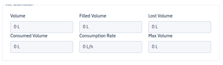
| Field | Unit | Description |
|---|---|---|
| Volume | l | Present tank volume |
| Filled Volume | l | Total filled volume |
| Lost Volume | l | Total lost volume |
| Consumed Volume | l | Total consumed volume |
| Consumption Rate | l/h | Current consumption rate |
| Max Volume | l | Configured tank capacity |
Genset Controls
| Control | Description |
|---|---|
| Operational Mode: Auto | Set genset to automatic operation |
| Operational Mode: Forced On | Force genset on |
| Operational Mode: Forced Off | Force all AC sources off |
| Runtime Reset | Set runtime to a specific value (hours) |
| Service Reset | Reset service countdown timer |
4.6 Solar Information
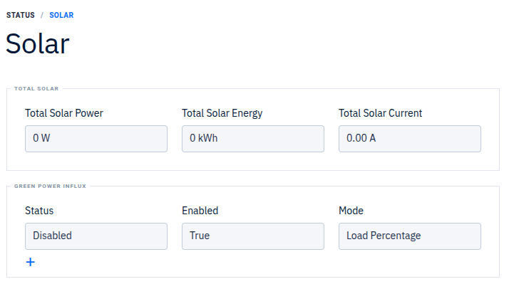
Total Solar
| Field | Unit | Description |
|---|---|---|
| Total Solar Power | W | Total produced power from all arrays |
| Total Solar Energy | kWh | Total produced energy |
| Total Solar Current | A | Total output current |
Green Power Influx (expandable section)
| Field | Unit | Description |
|---|---|---|
| Status | — | Current GPI status |
| Enabled | — | Whether GPI is enabled |
| Mode | — | Load Percentage or Time Interval |
| Voltage Enable | V | Activation voltage |
| Voltage Disable | V | Deactivation voltage |
| SOC Enable | % | Activation SoC |
| SOC Disable | % | Deactivation SoC |
| Load Power Pct Off | % | Load percentage to deactivate |
| Load Power Pct On | % | Load percentage to activate |
| Hour Enable / Disable | h | Time-based activation hours |
| Minute Enable / Disable | m | Time-based activation minutes |
Per-Array Data (up to 3 solar arrays)
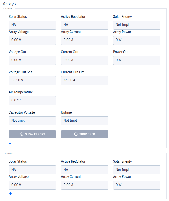
| Field | Unit | Description |
|---|---|---|
| Solar Status | — | Array operational status |
| Active Regulator | — | Active regulation mode |
| Solar Energy | kWh | Array energy production |
| Array Voltage | V | Input array voltage |
| Array Current | A | Input array current |
| Array Power | W | Input array power |
| Voltage Out | V | Output voltage |
| Current Out | A | Output current |
| Power Out | W | Output power |
| Voltage Out Set | V | Output voltage setpoint |
| Current Out Lim | A | Output current limit |
| Air Temperature | °C | Converter air temperature |
| Capacitor Voltage | V | Internal capacitor voltage |
| Uptime | — | Converter uptime |
Each array also has Show Errors and Show Info buttons for detailed diagnostics.
4.7 Grid Information
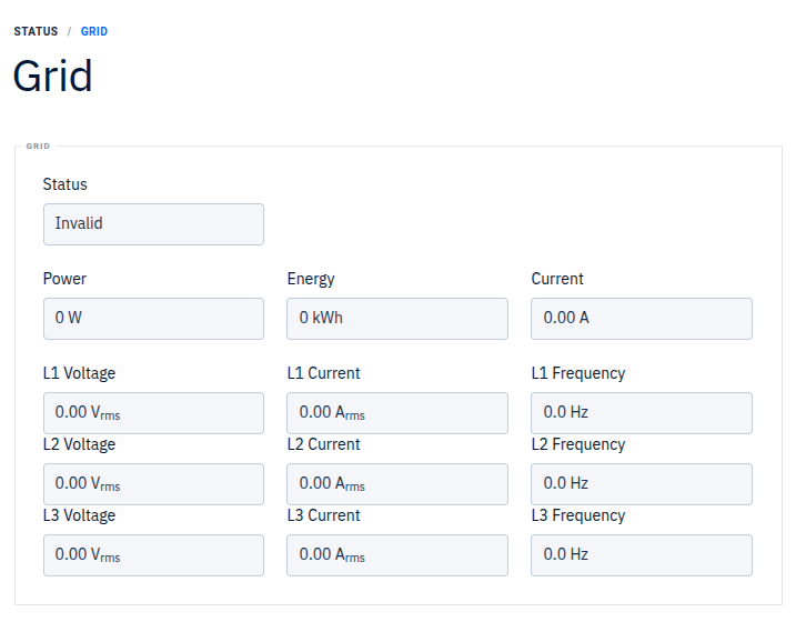
| Field | Unit | Description |
|---|---|---|
| Status | — | Invalid / Inhibited / Partial / Available |
| Power | W | Power drawn from grid |
| Energy | kWh | Total grid energy |
| Current | A | Produced DC current from grid |
Three-Phase Power (L1, L2, L3)
| Field | Unit |
|---|---|
| Voltage | Vrms |
| Current | Arms |
| Frequency | Hz |
4.8 Active Alerts
Active system alerts are displayed in a notification dropdown accessible from the bell icon in the top navigation bar. Each alert shows:
- Severity indicator: F (Fatal/danger), E (Error/warning), W (Warning/info)
- Event name
- Count (if multiple instances of the same event)
- Date and time of activation
4.9 CAN Diagnostics
The CAN Diagnostics page provides real-time monitoring of converter units and their CAN bus nodes.
Converter Unit Cards
Each registered converter unit is displayed as a card showing:
- Unit ID and serial number
- Configuration type badge (e.g., R3_S3, R2_S1 — indicating number of ACDC and SOLAR nodes)
- Error count badge (if errors exist)
- 3×2 grid of node status indicators
Node Status
Each node (ACDC 1–3, SOLAR 1–6) shows:
- Status color: Green (OK), Red with animation (Error/Timeout), Gray (empty slot)
- Clicking a node opens a detail modal
Node Detail Modal
| Field | Description |
|---|---|
| Unit ID | Parent converter unit |
| Serial | Node serial number |
| Status | Ok / Pending / Missing / Timeout (with duration) |
Actions:
- Ping — Send a CAN ping to the node
- Reset — Reset the node via CAN
Node status auto-refreshes every 5 seconds.
4.10 Converter Units
The Converter Units page displays all detected converter units with their registration status.
| Column | Description |
|---|---|
| Unit Serial Number | Device serial number |
| Communications Status | Okay / Not Okay |
| Registration Status | Registered / Not Registered |
| Control | Register or Unregister button |
A maximum of 3 units can be registered simultaneously. When the system is in Registration Mode (system_mode = 6), a warning banner is displayed.
Warning: Before unregistering a unit, switch off all AC/Solar power input to the system. The unit must not be actively converting at the time of unregistering.
4.11 Settings
Settings are accessed from the sidebar. Each settings page displays current values and allows entering new values. Click Confirm to apply changes.
When a setting is changed via the web UI, the new value is written to the site_data SQLite database and the PD Manager process is notified via IPC. PD Manager then propagates the change to the control algorithm via shared memory.
4.11.0 Setting User Interface
4.11.0.1 Confirm Configuration Changes
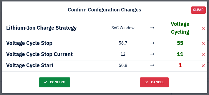
Confirm button:
Confirms the setting changes and starts the process of writing the changes to the RMC, unless any of the settings has failed the pre range-check indicated by a pulsing red number/text on the right-hand side of the arrow.
Example of a failed pre range-check is shown here #id-4.11.0.1-confirm-configuration-changes for the "Voltage Cycle Start" setting.
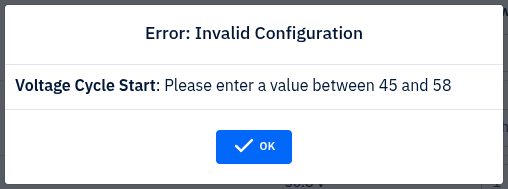
If any of the setting changes fails the pre range-check the settings wont be removed from this list but the list will be hidden and the user will be shown an error message. Example: #id-4.11.0.2-configuration-change-error
Cancel button:
Will close the Confirm Configuration Changes window. Setting in the list will be saved and the window can simply be shown again by pressing the confirm button on the bottom left hand side of the page.
Clear Button:
Will remove all settings from the list and close the confirm configurations changes window.
Per setting cross-button:
Will remove the setting on the corresponding row from the list and prevent it from being changed.
4.11.0.2 Configuration Change Error
4.11.0.3 Graph Style Setting
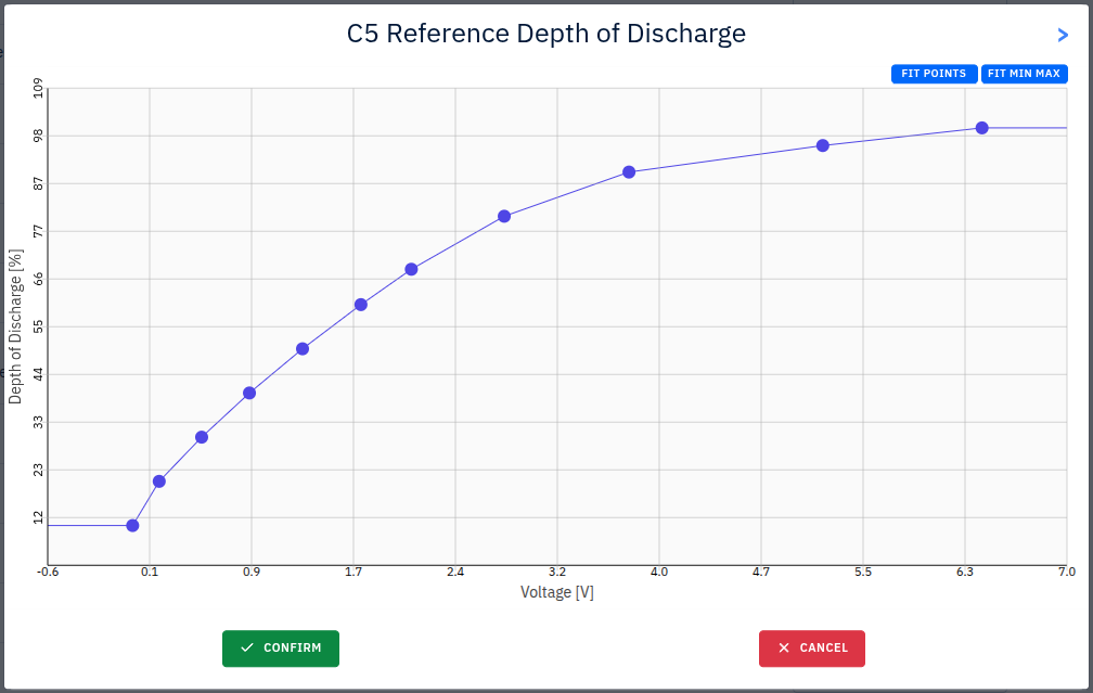
Example of a graph-style setting with movable points.
Functionality:
- Scroll up: Zoom in
- Scroll down: Zoom out
- Scroll on X axis: Vertical zoom in/out
- Scroll on Y axis: Horizontal zoom in/out
- Drag on graph area: Move graph area
- Double click: Resize graph area to min/max value of X and Y
Fit Points Button: Fit all points in the graph area
Fit Min Max: Resize graph area to min/max value of X and Y
Arrow Button (top-right corner): Extends window to show points in a table format, see #id-4.11.0.4-graph-style-setting-extended-points
4.11.0.4 Graph Style Setting Extended Points
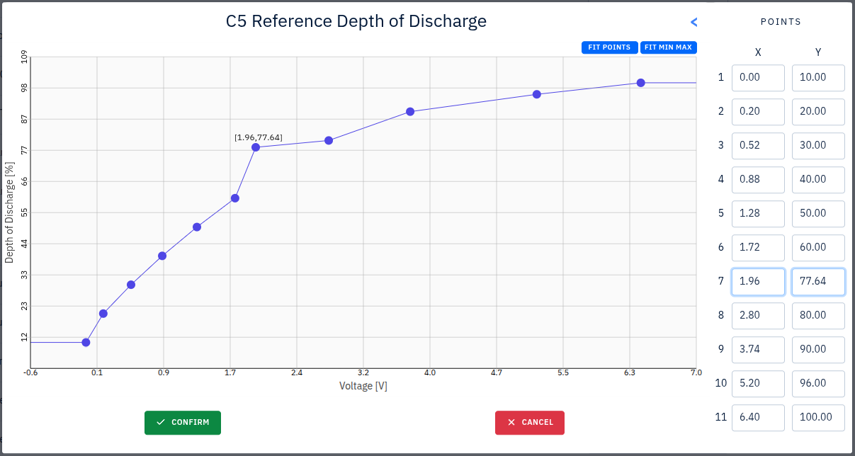
Extra functionality extended points:
- When dragging any point: Highlights point in table
- When editing value of a point in table section: Highlights point in graph area
4.11.1 Setting Relationships and Dependencies
Understanding how settings interact is critical for correct system configuration. The diagram below shows the major dependency chains:
├─► AC Source Selection (Source A / Source B)
│     ├─► Determines which Status pages appear (Grid, Genset 1, Genset 2)
│     ├─► Controls which Genset Settings sections are visible
│     ├─► Sets rectifier current limits and power source arbitration
│     └─► Affects Digital Output assignment (Source B = Genset2 → DO2 = 3)
│
├─► Battery Type Selection
│     ├─► Determines available Charge Strategies (Lead-Acid: 3, Li-ion: 2)
│     ├─► Loads strategy-specific parameters (voltage, SoC, current limits)
│     ├─► Sets default temperature alarm thresholds from battery template
│     └─► Controls which charge modes are available (Balancing for Li-ion, Equalize for Lead-Acid)
│
├─► Charge Strategy → Parameter Visibility
│     ├─ Voltage Cycling → Shows cycle start/stop voltages and timing
│     ├─ Static SoC → Shows SoC window start/stop percentages
│     └─ Partial SoC → Shows partial SoC parameters (Lead-Acid only)
│
├─► Cabinet Cooling Mode → Which temperature thresholds are editable
│     ├─ Delta Ambient → Delta Fan On/Off fields
│     └─ Battery Temp Levels → Absolute temperature Fan On/Off fields
│
├─► Modbus Server Enable → Disables BMU and Genset Modbus communication
│
└─► Fuel Sensor Type → Which tank dimension and calibration fields appear
      ├─ Height sensor → Tank shape + dimensions
      ├─ Litre sensor → Max litre capacity
      └─ Lookup sensor → 10-point voltage-to-litre calibration table
Key interaction rules:
- AC Source A and B are mutually exclusive for certain combinations (e.g., both cannot be the same genset).
- Changing the battery type reloads all charge parameters from the selected battery template database.
- Enabling the Modbus Server disables direct BMU and genset Modbus RTU communication.
- Night Silence, Hybrid Shifting, and Peak Load Shifting each define time windows that affect genset and grid behavior — overlapping windows should be configured carefully.
4.11.2 General Settings
These identify the site and configure the system clock. The Micro Name and ID are transmitted to the Illumience cloud platform for remote identification. Changing the timezone triggers a systemctl restart sysconfig to apply the new zone system-wide.
| Setting | Type | Description |
|---|---|---|
| Micro Name | Text (max 40 chars) | Human-readable site name, displayed on dashboard and sent to cloud |
| Micro ID | Text (max 40 chars) | Unique site identifier used by Illumience for remote management |
| Timezone | Dropdown | IANA timezone — affects all time-based features (Night Silence, Hybrid Shifting, Peak Load Shifting schedules, event timestamps) |
| Time | HH:MM:SS | Set system time (also syncs to hardware clock via hwclock --systohc) |
| Date | YYYY-MM-DD | Set system date |
4.11.3 Rectifier (AC Source) Settings
The rectifier converts AC power (from gensets or grid) into DC power for battery charging. Source A and Source B define the two AC input paths. The system uses source arbitration to select the active input based on availability and priority, with automatic fallback if the primary source becomes unavailable.
The PI compensator implements closed-loop current regulation for battery charging. Increasing P Gain improves response speed but may cause oscillation; increasing I Gain eliminates steady-state error but may cause overshoot. Max/Min Range limits the compensator output to prevent damage.
The CPU Temperature Derate curve progressively reduces rectifier output power as the converter CPU heats up, preventing thermal shutdown. When temperature exceeds configured thresholds, alarms are raised and power output is reduced according to the derate curve.
| Setting | Type | Options/Range | Unit | What it does |
|---|---|---|---|---|
| AC Source (A) | Dropdown | None, Genset 1, Genset 2, Grid | — | Primary AC input path. Determines which external power source charges the battery. When set, the corresponding Status page (Grid/Genset) becomes visible in the sidebar. |
| AC Source (B) | Dropdown | None, Genset 1, Genset 2, Grid | — | Secondary AC input path (requires SAS license). Enables dual-source redundancy. If Source B is set to Genset 2, Digital Output 2 is automatically assigned to genset 2 control. |
| Current Compensator P Gain | Number | 0–100 | — | Proportional gain of the charging current PI controller. Higher = faster current response but risk of oscillation. |
| Current Compensator I Gain | Number | 0–100 | — | Integral gain of the charging current PI controller. Higher = eliminates steady-state current error but risk of overshoot. |
| Current Compensator Max Range | Number | 0–100 | A | Upper clamp on compensator output — maximum corrective current the regulator can add. |
| Current Compensator Min Range | Number | -100–0 | A | Lower clamp on compensator output — maximum corrective current the regulator can subtract. |
| CPU Temperature Derate | Graph | X: 0–100°C, Y: 0–3500W | — | Lookup curve mapping converter CPU temperature to maximum allowed output power. As temperature rises, output is progressively reduced. |
4.11.4 Battery Settings
Battery settings is a large configuration page covering battery profiles, charge strategies, and detailed electrical parameters.
Battery Profile: Select from a dropdown of predefined battery configurations (30+ types including AR400, AR600, LG Chem, Vision, Narada, Polarium, etc.). Selecting a profile loads all charge parameters, alarm thresholds, and strategy options from a dedicated battery template database.
Battery Chemistry: Lithium-Ion or Lead-Acid. This fundamentally changes which parameters and charge modes are available.
Charge Strategy: Determines how the control algorithm manages battery charge/discharge cycles:
- Voltage Cycling (Lead-Acid & Li-ion): The most traditional approach. Charges the battery by monitoring voltage levels through absorption and float phases. Uses temperature-compensated voltage setpoints. The cycle starts when battery voltage drops below Start Voltage and stops when it reaches Stop Voltage for the configured Stop Time at or below Stop Current.
- Static SoC (Lead-Acid & Li-ion): Maintains battery State of Charge within a fixed window. Charging starts when SoC drops below Window Start % and stops when SoC reaches Window Stop %. Keeps the battery at a constant operational range, reducing deep discharge stress. For Li-ion, an additional "Balancing SoC" option is available that incorporates cell balancing.
- Partial SoC (Lead-Acid only): Cycles the battery between partial charge levels rather than full cycles. Reduces stress from full charge/discharge, extending battery life. Better for long-term health at the cost of reduced usable capacity per cycle.
Key parameter groups (fields vary by chemistry and charge strategy):
| Parameter Group | Fields | What they do |
|---|---|---|
| Voltage Cycling | Start voltage, Stop voltage, Stop current, Stop time | Start voltage triggers a charge cycle; Stop voltage + Stop current + Stop time define when the cycle ends (all three conditions must be met). |
| Static SoC | Window start %, Window stop % | Defines the SoC band the battery operates within. Charging begins at Window Start and ends at Window Stop. |
| Partial SoC | SoC window, Stop current, Stop voltage, Inhibit stop % | Similar to Static SoC but with partial charge targets. Inhibit stop prevents premature cycle termination below a threshold. |
| Full Charge | Time interval, Energy throughput, Trigger voltage | A full charge (6+ hours genset) is triggered when: time since last full charge exceeds the interval, OR cumulative energy throughput exceeds the threshold, OR voltage drops below the trigger voltage. Full charges condition the battery and recalibrate SoC estimation. |
| Charge Voltages | Genset/Grid/Solar boost/float/set voltages | Different voltage setpoints depending on the active power source. Boost voltage is the higher absorption-phase target; float voltage is the lower maintenance target. Solar, genset, and grid each have independent setpoints because their power characteristics differ. |
| Current Limits | Nominal current, Max charge current, Safe mode current | Nominal is the normal charging current. Max is the absolute ceiling. Safe mode current is a severely reduced limit used when sensor failures or fuse trips are detected — protects the battery when the system cannot accurately monitor conditions. |
| Temperature Compensation | X0–X3 (°C), Y0–Y3 (V) — Lead-Acid only | A 4-point lookup table that adjusts charge voltage based on battery temperature. Cold batteries need higher voltage to fully charge; hot batteries need lower voltage to avoid gassing. The control algorithm interpolates between points. Critical for lead-acid battery health and longevity. |
| Li-ion Specific | Ramp up voltage/time, Synchronization current/time, Balancing parameters | Ramp Up: Gradually increases current at startup to prevent shock to the battery pack. Configured by target voltage and duration. Synchronization: Aligns charge state across multiple battery modules before main charging begins, using a low current for a configured duration. Balancing: Periodically charges to 100% with active cell balancing to equalize all cells. Triggered by energy throughput, cycle count, or voltage thresholds. |
| Battery Alarms | High temp, Very high temp, Low voltage, Low voltage reset | Threshold-based alarms. Low voltage reset is a hysteresis value — the alarm clears only when voltage rises above this level, preventing alarm chatter near the threshold. Temperature alarms are loaded from the battery template and can be customized. |
Charge Modes (automatic and manual):
| Mode | Trigger | Duration | Description |
|---|---|---|---|
| Normal Charge | Automatic (strategy-dependent) | Varies | Default mode — responds to battery needs per the selected charge strategy |
| Full Charge | Time interval / voltage trigger / manual button | ~6 hours | Deliberately charges to 100% SoC for battery conditioning and SoC recalibration |
| Extended Full Charge | Manual button (requires no customer load) | ~24 hours | Complete battery conditioning cycle for severely degraded batteries |
| Safe Mode | Automatic (sensor failure or fuse trip) | Until fault clears | Severely limits charge current for safety when monitoring is unreliable |
| Ramp Up (Li-ion) | Automatic at startup | Configured duration | Gradual current increase to protect cold or new battery packs |
| Synchronization (Li-ion) | Automatic after ramp up | Configured duration | Aligns charge across multiple BMU modules before main charge |
| Balancing Full Charge (Li-ion) | Energy/cycle/voltage triggers or manual | Until balanced | Full charge with cell-level balancing to equalize all cells |
Save and Load configuration buttons allow exporting/importing battery profiles.
4.11.5 Solar Settings (Green Power Influx)
Green Power Influx (GPI) is a mode that prioritizes renewable energy sources (solar) for battery charging. When enabled and all trigger conditions are met, the system preferentially uses solar power and may inhibit genset starts. This reduces fuel consumption during periods of high solar availability.
GPI uses a multi-condition trigger — all configured conditions must be satisfied simultaneously for the mode to activate:
| Setting | Type | Options/Range | Unit | What it does |
|---|---|---|---|---|
| Green Power Mode Enabled | Dropdown | False, True | — | Master enable for the GPI feature |
| Green Power Mode | Dropdown | Load Percentage, Time Interval | — | Load Percentage: Activates based on how much load the system has relative to solar production. Time Interval: Activates during a configured daily time window (typically daylight hours). |
| Load Power Percentage On | Number | 0–200 | % | GPI activates when load power drops below this percentage of solar capacity (low load = excess solar available) |
| Load Power Percentage Off | Number | 0–200 | % | GPI deactivates when load power rises above this percentage (high load = solar insufficient) |
| GPI Time | Number | 0–7200 | s | Delay before entering GPI mode after all trigger conditions are met — prevents rapid mode switching from transient conditions |
| Time Enable | Time | HH:MM | — | Daily start time for GPI window (Time Interval mode) |
| Time Disable | Time | HH:MM | — | Daily end time for GPI window (Time Interval mode) |
| GPI Voltage Enable | Number | 0–60 | V | GPI activates when DC bus voltage rises above this level (high voltage = excess solar charging) |
| GPI Voltage Disable | Number | 0–60 | V | GPI deactivates when DC bus voltage drops below this level |
| GPI SoC Enable | Number | 0–100 | % | GPI activates when battery SoC exceeds this level (battery sufficiently charged) |
| GPI SoC Disable | Number | 0–100 | % | GPI deactivates when battery SoC drops below this level (battery needs charging from any source) |
4.11.6 Grid Settings
Fuse: Sets the maximum current the grid rectifier is allowed to draw per phase. This protects the site's grid connection and upstream breakers.
| Setting | Type | Range | Unit |
|---|---|---|---|
| Grid Max Fuse | Number | 1–19 | A |
Per-Phase Settings (Phase A, B, C):
These are hysteresis thresholds that determine when the grid is considered healthy or unhealthy on each phase. The system monitors all three phases independently. If any phase goes out of range, the grid source may be inhibited.
- Low/High Voltage On/Off: The "On" threshold triggers a state change (e.g., grid inhibited) when voltage crosses that level. The "Off" threshold clears the state. The gap between On and Off provides hysteresis to prevent rapid switching when voltage fluctuates near a threshold.
- Low/High Frequency On/Off: Same hysteresis logic for frequency. Frequency deviation from 50/60 Hz indicates grid instability or generator issues.
| Setting | Type | Range | Unit | What it does |
|---|---|---|---|---|
| Low Voltage On | Number | 0–400 | V | Grid inhibited when phase voltage drops below this (undervoltage protection) |
| Low Voltage Off | Number | 0–400 | V | Grid re-enabled when phase voltage rises above this (must be > Low Voltage On for hysteresis) |
| High Voltage On | Number | 0–400 | V | Grid inhibited when phase voltage exceeds this (overvoltage protection) |
| High Voltage Off | Number | 0–400 | V | Grid re-enabled when phase voltage drops below this |
| Low Frequency On | Number | 0–100 | Hz | Grid inhibited when frequency drops below this |
| Low Frequency Off | Number | 0–100 | Hz | Grid re-enabled when frequency rises above this |
| High Frequency On | Number | 0–100 | Hz | Grid inhibited when frequency exceeds this |
| High Frequency Off | Number | 0–100 | Hz | Grid re-enabled when frequency drops below this |
Peak Load Shifting:
During peak demand periods (defined by the time window), the system raises the grid float voltage setpoint. This reduces load drawn from the grid, lowering peak demand charges from the utility. The battery absorbs more of the load during peak hours.
| Setting | Type | Options/Range | Unit | What it does |
|---|---|---|---|---|
| Enabled | Dropdown | False, True | — | Master enable for peak load shifting |
| On Time | Time | HH:MM | — | Start of peak period (e.g., 08:00) |
| Off Time | Time | HH:MM | — | End of peak period (e.g., 20:00) |
| Shifting Voltage | Number | 0–100 | V | Grid float voltage during peak hours — higher voltage means less grid draw |
4.11.7 Genset Settings
The genset (generator set) is an AC power source that charges the battery when solar/grid is insufficient. The control algorithm manages genset startup sequences, power ramping, and shutdown with configurable timing to protect the engine and prevent fuel waste. Genset settings are only visible when AC Source A or B is configured to a genset.
| Setting | Type | Range | Unit | What it does |
|---|---|---|---|---|
| Minimum Runtime | Number | 0–99999 | s | Once started, the genset must run for at least this long before it can be stopped. Prevents short runs that waste fuel, increase wear, and accumulate carbon deposits in the engine. |
| Exercise Run Enabled | Dropdown | False, True | — | Enables periodic automatic genset startups to prevent fuel degradation (stale fuel), ensure starting reliability, and lubricate engine internals. Critical for sites where the genset may not run for weeks. |
| Exercise Interval | Number | 0–4294967295 | h | Hours between automatic exercise runs. Typical: 168–720 hours (weekly to monthly). |
| Exercise Duration | Number | 0–4294967295 | s | How long the genset runs during each exercise. Should be long enough to reach operating temperature. |
Per-Genset (Genset 1, Genset 2):
The startup/shutdown sequence follows this order: Start → Warmup → Ramp-up → Run → Ramp-down → Cooldown → Off-delay → Stopped. Each phase has a configurable duration.
| Setting | Type | Range | Unit | What it does |
|---|---|---|---|---|
| Rated Power | Number | 0–99999 | kVA | Nominal power rating of the genset. Used with Power Factor to calculate ramp rates and maximum power requests. |
| Warmup | Number | 0–600 | s | Time after ignition before the genset accepts load. Allows fuel/ignition stabilization and engine temperature to rise. |
| Ramp-up | Number | 0–600 | s | Time to gradually increase power output from zero to rated capacity. Power ramp rate = (Rated Power × Power Factor) / Ramp-up time. Prevents shock loading. |
| Ramp-Down | Number | 0–600 | s | Time to gradually reduce power output before shutdown. Prevents abrupt load removal. |
| Cooldown | Number | 0–600 | s | Time the genset continues running at idle after load is removed. Allows internal engine cooling to prevent thermal shock (hot shutdown can damage turbochargers and gaskets). |
| Off | Number | 0–3600 | s | Delay after cooldown before the genset is fully shut down. Allows control signals to propagate and prevents rapid on/off cycling. |
| Service | Number | 0–4294967295 | h | Service interval countdown. When runtime reaches this value, a service alarm is raised. Resettable from the Genset Information page. |
| Power Factor | Number | 0–100 | % | Ratio of real power (W) to apparent power (VA). Used with Rated Power to calculate the actual power available: Real Power = Rated Power × Power Factor / 100. |
Hybrid Shifting:
Hybrid shifting reduces fuel consumption during periods when renewable sources (solar) are expected to be available. During the configured time window, the genset stop voltage setpoint is raised, causing the genset to stop earlier and allow the battery to float on solar power. Typically configured for daylight hours.
| Setting | Type | Range | Unit | What it does |
|---|---|---|---|---|
| Shifting On Time | Time | HH:MM | — | Start of the hybrid shifting window (e.g., sunrise) |
| Shifting Off Time | Time | HH:MM | — | End of the hybrid shifting window (e.g., sunset) |
| Stop Voltage | Number | 0–100 | V | Genset stop voltage during the shifting window — set higher than normal so the genset shuts off earlier, allowing renewables to take over |
4.11.8 Load Control (Load Disconnect)
Load control protects the battery from deep discharge by disconnecting loads when battery voltage drops too low. The system has two load tiers: Low Priority loads are shed first (at higher voltage), and High Priority loads are shed only if the battery continues to drop further. Both voltage AND current conditions must be met for reconnection — this prevents reconnecting when the system cannot support additional load.
Low Priority Load:
| Setting | Type | Range | Unit | What it does |
|---|---|---|---|---|
| Disconnect Voltage | Number | 42–60 | V | When battery voltage drops below this level, low priority loads are disconnected to preserve battery charge for critical loads. |
| Disconnect Time | Number | 0–4294967295 | s | Delay before disconnecting after voltage drops below threshold — prevents disconnection from brief voltage dips (e.g., genset starting). |
| Reconnect Voltage | Number | 42–60 | V | Battery voltage must rise above this level before loads are reconnected. Set higher than Disconnect Voltage to provide hysteresis. |
| Reconnect Time | Number | 0–4294967295 | s | Delay after voltage recovery before reconnecting — ensures voltage is stable, not just a momentary spike. |
| Reconnect Current | Number | 0–200 | A | Charge current must also be above this level for reconnection. Ensures the power source can sustain the additional load. |
| Fast Reconnect Voltage | Number | 42–60 | V | If voltage rapidly rises above this (higher) threshold, loads reconnect immediately without waiting for the Reconnect Time delay. Useful when a genset starts and quickly raises the bus voltage. |
High Priority Load:
| Setting | Type | Options/Range | Unit | What it does |
|---|---|---|---|---|
| Enabled | Dropdown | False, True | — | Master enable — when disabled, low priority settings are inheirited |
| Disconnect Voltage | Number | 42–60 | V | Should be lower than Low Priority disconnect voltage (these are the last loads to be shed). |
| Disconnect Time | Number | 0–4294967295 | s | Delay before disconnecting high priority loads. |
| Reconnect Voltage | Number | 42–60 | V | Voltage threshold for reconnecting high priority loads. |
| Reconnect Time | Number | 0–4294967295 | s | Delay after voltage recovery before reconnecting high priority loads. |
4.11.9 Cabinet Cooling
Controls the battery cabinet ventilation fan. The mode selection determines which temperature thresholds are used. If the temperature sensor fails, the system enters a Fallback mode and forces the fan on as a safety measure.
| Setting | Type | Options/Range | Unit | What it does |
|---|---|---|---|---|
| Cabinet Cooling Mode | Dropdown | No Cabinet Cooling, Delta Ambient, Battery Temperature Levels | — | No Cooling: Fan always off. Delta Ambient: Fan activates based on the temperature difference between battery and ambient — useful when ambient is cool but batteries generate heat. Battery Temperature Levels: Fan activates at fixed battery temperature thresholds — simpler, for environments with stable ambient. |
| Temperature Delta Fan On | Number | 0–100 | °C | (Delta Ambient mode) Fan turns on when (Battery Temp − Ambient Temp) ≥ this value |
| Temperature Delta Fan Off | Number | 0–100 | °C | (Delta Ambient mode) Fan turns off when (Battery Temp − Ambient Temp) ≤ this value. Must be < Fan On for hysteresis. |
| Battery Temperature Fan On | Number | 0–100 | °C | (Battery Temp Levels mode) Fan turns on when battery temperature ≥ this value |
| Battery Temperature Fan Off | Number | 0–100 | °C | (Battery Temp Levels mode) Fan turns off when battery temperature ≤ this value |
| CPU Temperature Cooling Trigger | Number | 0–200 | °C | When converter CPU temperature exceeds this, rectifier power derating begins. Also triggers cooling alarms. |
| Minimum Run Time | Number | 0–10000 | s | Once the fan starts, it must run for at least this long before stopping. Prevents rapid on/off cycling that damages the fan motor and reduces cooling effectiveness. |
Fields are conditionally visible based on the selected cooling mode.
4.11.10 Input/Output Configuration
Maps physical digital inputs on the hardware to system functions. Each input can be assigned to monitor a specific external signal. The system reads the input state and generates events/alarms accordingly.
Digital Inputs (DI 1–9):
Each input has:
| Setting | Type | Options | What it does |
|---|---|---|---|
| Function | Dropdown | See below | Assigns the physical input to a monitoring function |
| State | Dropdown | Normally Closed, Normally Open | Defines the default (inactive) state of the circuit. Normally Closed: the circuit is closed when inactive — an open circuit triggers the alarm. Normally Open: the circuit is open when inactive — a closed circuit triggers the alarm. |
Digital Input Functions:
| Function | Description |
|---|---|
| Not Used | Input is ignored |
| Digital Input | Generic digital input — state is logged but no specific action |
| Surge Protection | Monitors surge/lightning protector status. Alarm raised if protector is tripped (needs replacement). |
| MCB Battery Bank | Monitors the battery bank circuit breaker (MCB). Alarm if breaker trips, indicating a short circuit or overcurrent in the battery bank. |
| Battery Door | Monitors the battery cabinet door sensor. Alarm when door is open — useful for tamper detection and environmental control. |
| Genset 1 Ext Alarm 1–3 | Three external alarm inputs from Genset 1's controller. Maps external genset faults (low oil, high temp, etc.) into the RMC alarm system. |
| Genset 2 Ext Alarm 1–3 | Same as above for Genset 2. |
4.11.11 Network Configuration
Configures the eth0 network interface. Changes trigger systemctl start set-ip-address to apply. Since the web interface is accessed over this network, incorrect settings will lock you out.
| Setting | Type | Validation | Description |
|---|---|---|---|
| IP Address | Text | IPv4 CIDR format (e.g., 192.168.1.1/24) | Static IP address with subnet mask for the eth0 interface |
| IP Gateway | Text | IPv4 or "NONE" | Default gateway for outbound traffic. Set to "NONE" for isolated networks. |
| VLAN ID | Text | 0–4095 or "NONE" | 802.1Q VLAN tag. Used when the RMC shares a network trunk with other equipment requiring VLAN segmentation. "NONE" disables VLAN tagging. |
Warning: Changing network settings may cause loss of connection. Ensure you have physical access to the device.
4.11.12 Alarm Settings
All alarms use temporal debouncing (configurable delays or internal counters) to prevent false triggers from transient conditions. The event handler records alarms in the event database with timestamps and severity levels.
Load Alarms:
| Setting | Range | Unit | What it does |
|---|---|---|---|
| Total Max Load | 0–10000 | W | Alarm when total system load exceeds this value + hysteresis |
| High Priority Max Load | 0–10000 | W | Alarm when high priority load alone exceeds this value |
| Load Hysteresis | 0–1000 | W | Prevents alarm chatter from load fluctuations near the threshold. Alarm activates when load exceeds (Max + Hysteresis), clears when load drops below Max. |
Tenant Alarms (Tenant 1–10):
Each tenant (individually metered customer on the site) has its own load alarm. This prevents one tenant from overloading the system without being identified.
| Setting | Range | Unit | What it does |
|---|---|---|---|
| Tenant [1–10] Max Load | 0–9500 | W | Per-tenant power consumption alarm threshold |
| Tenant Alarm Delay | 0–300 | s | How long a tenant must exceed their threshold before the alarm triggers. Allows brief spikes (e.g., motor startup) without false alarms. |
Voltage Alarms:
| Setting | Range | Unit | What it does |
|---|---|---|---|
| High Battery Voltage | 0–70 | V | Alarm when battery voltage exceeds this — indicates overcharging or rectifier malfunction |
| Low Battery Voltage | 0–60 | V | Alarm when battery voltage drops below this — indicates deep discharge or insufficient charging |
| Low Voltage Alarm Reset | 0–60 | V | The low voltage alarm only clears when voltage rises above this level. Must be higher than Low Battery Voltage to provide hysteresis and prevent the alarm from flickering on/off. |
Temperature Alarms:
| Setting | Range | Unit | What it does |
|---|---|---|---|
| Max Average Temperature | 0–70 | °C | Alarm when the average battery temperature over the configured time period exceeds this value. Detects sustained thermal issues that instantaneous readings might miss. |
| Temperature Time Period | 0–8760 | h | The rolling window (in hours) over which the average temperature is calculated. 1 hour = detect recent spikes; 8760 hours (1 year) = detect seasonal trends. Typical: 24–168 hours. |
| Battery High Temperature | 0–70 | °C | Instantaneous alarm when battery temperature exceeds this. Default values are loaded from the selected battery template. |
| Battery Very High Temperature | 0–70 | °C | Critical alarm at a higher threshold — may trigger protective actions like reduced charge current. |
| Battery Cooling Temperature Delta High | 0–70 | °C | Alarm when (Battery Temp − Ambient Temp) exceeds this value, indicating the cooling system cannot keep up with heat generation. |
| Poor Battery Cooling Alarm Enabled | False / True | — | Enables the "Poor Battery Cooling" alarm. When active, triggers if the temperature delta exceeds the threshold above, warning that cooling capacity is insufficient and thermal runaway risk may exist. |
Fuel Alarms:
| Setting | Range | Unit | What it does |
|---|---|---|---|
| Low Fuel Level | 0–10000 | l | Warning alarm when tank volume drops below this level. Allows time to schedule a fuel delivery. |
| Very Low Fuel Level | 0–10000 | l | Critical alarm at a lower threshold — genset may run out of fuel soon. |
| Low Fuel Level Hysteresis | 0–10000 | l | The alarm clears when fuel level rises above (Low Fuel Level + Hysteresis). Prevents alarm flickering when fuel sloshes near the threshold level. |
Genset Service Alarms:
| Setting | Range/Options | What it does |
|---|---|---|
| Genset Service Enabled | False / True | Enables service interval tracking and alarms |
| Service Time | 0–10000 | Hours of runtime after which a service alarm is raised (oil change, filter replacement, etc.). The countdown is tracked per-genset and is resettable from the Genset Information page. |
| Failure Time | 1–10000 | Hours of runtime after which a failure/critical alarm is raised if the service alarm was not addressed. Indicates overdue maintenance. |
4.11.13 Fuel Monitor Settings
Monitors fuel levels in genset tanks using analog sensors. The system converts raw sensor readings (voltage) into fuel volume using the configured sensor type, tank geometry, and calibration data. Each tank is independently configured and can be linked to a specific genset for per-genset fuel consumption tracking.
Configured per tank (Tank 1, Tank 2). Each tank has:
| Setting | Type | Options/Range | Unit | What it does |
|---|---|---|---|---|
| System Option | Dropdown | Basic, Medium, Large | — | Selects the installation scale. Affects which tank configurations and sensor options are available. |
| Usage Threshold | Number | 0–100 | % | Percentage of tank capacity change that constitutes "significant usage" for consumption rate calculations. Filters out noise from sensor fluctuations. |
| Usage Time | Number | 0–100000 | s | Time window for measuring fuel consumption rate. The system calculates liters consumed over this period to determine l/h consumption rate. |
| Filter Length | Number | 0–100000 | — | Number of samples for moving-average filter on the raw sensor reading. Higher values = smoother but slower-responding readings. Filters out fuel sloshing and sensor noise. |
| Connected Genset | Dropdown | Genset 1, Genset 2, Disabled | — | Links this tank to a genset for consumption tracking. When linked, the Genset Information page shows this tank's fuel data. |
| Sensor Type | Dropdown | See below | — | Determines how the raw analog signal is converted to fuel volume |
| Sensor Max Output Voltage | Number | 0–10 | V | Voltage output from the sensor at maximum fuel level (full tank) |
| Sensor Min Output Voltage | Number | 0–10 | V | Voltage output from the sensor at minimum fuel level (empty tank) |
| Sensor Range Max Height | Number | 0–10 | m | (Height sensor) Maximum measurable fuel height corresponding to Max Output Voltage |
| Sensor Range Max Litre | Number | 0–50000 | l | (Litre sensor) Maximum volume corresponding to Max Output Voltage |
| Tank Shape | Dropdown | Rectangular Box, Standing Cylinder, Horizontal Cylinder | — | (Height sensor) Determines the volume calculation formula — see below |
| Tank Height | Number | 0–10000 | m | Tank height dimension (all shapes) |
| Tank Length | Number | 0–10000 | m | Tank length (Rectangular Box and Horizontal Cylinder) |
| Tank Width | Number | 0–10000 | m | Tank width (Rectangular Box only) |
| Tank Radius | Number | 0–10000 | m | Tank radius (Standing and Horizontal Cylinder) |
| Tank Lookup | Graph/Table | — | — | (Lookup sensor) 10-point calibration table mapping sensor voltage (X) to fuel volume in litres (Y). The system interpolates between points for non-tabulated voltages. |
Sensor Types Explained:
| Sensor Type | How it works |
|---|---|
| No Sensor | Fuel monitoring disabled for this tank |
| Height | Analog voltage proportional to fuel height. Volume is calculated from height + tank geometry: Rectangular: V = L × W × H; Standing Cylinder: V = π × R² × H; Horizontal Cylinder: Complex partial-fill formula accounting for circular cross-section. |
| Litre | Analog voltage directly proportional to fuel volume. Linear scaling between min/max voltage and 0/max litres. |
| Lookup | Non-linear sensor or irregular tank shape. Uses a 10-point voltage-to-litre calibration table for accurate conversion. Compensates for sensor non-linearity and unusual tank geometries. |
| Modbus Genset 1/2 Litre/Percentage | Fuel level read via Modbus from the genset controller rather than an analog sensor. Available when genset Modbus communication is enabled. |
4.11.14 Night Silence
Night Silence prevents genset startups during sleeping hours to reduce noise pollution at the site. The system runs on battery power alone during the silent period. Safety thresholds ensure the battery doesn't discharge to a dangerous level — if voltage or SoC drops below the configured minimums, the genset is allowed to start and the silent period ends early.
The Safety Capacity setting is used to calculate whether the battery has enough energy to last through the remaining silent period. If estimated autonomous energy is insufficient, the genset starts despite the silence window.
| Setting | Type | Options/Range | Unit | What it does |
|---|---|---|---|---|
| Enabled | Dropdown | False, True | — | Master enable for night silence |
| Time Start | Time | HH:MM | — | Start of the silent period (e.g., 22:00) |
| Time Stop | Time | HH:MM | — | End of the silent period (e.g., 06:00). Can span midnight. |
| Stop Voltage | Number | 0–60 | V | Emergency exit threshold — if battery voltage drops below this during the silent period, the genset starts. Set higher than the normal genset start voltage to maintain a safety margin. |
| Stop State of Charge | Number | 0–100 | % | Emergency exit threshold — if battery SoC drops below this, the genset starts. |
| Stop on Charge Request | Dropdown | Disabled, Enabled | — | When enabled, blocks charge requests from other subsystems during the silent period. When disabled, charge requests (e.g., from BMS) can override night silence and start the genset. |
| Safety Capacity | Number | 0–99999 | Ah | Minimum battery reserve (in Ah) that must be maintained. The system calculates whether remaining capacity can sustain the load until the silent period ends — if not, the genset starts early. |
4.11.15 Modbus Server
The Modbus Server exposes the RMC's data registers to external systems (SCADA, building management, remote monitoring) via the Modbus protocol. External systems can read operational data and write control commands.
Important: Enabling the Modbus Server disables direct BMU and genset Modbus RTU communication on the same serial bus, since the RMC switches from master to slave role. Changes trigger systemctl restart modbus-handler.
| Setting | Type | Options/Range | Unit | What it does |
|---|---|---|---|---|
| Enabled | Dropdown | False, True | — | Enables the Modbus slave/server. When enabled, the RMC responds to Modbus requests from external masters. |
| Communication Protocol | Dropdown | Modbus RTU, Modbus TCP | — | RTU: Serial communication over RS-485 — used for local wired connections. TCP: Network-based communication over Ethernet — used for remote or IP-based SCADA integration. |
| Port | Number | 0–65535 (TCP only) | — | TCP port to listen on. Standard Modbus TCP port is 502. |
| Node ID | Number | 0–1000 (RTU only) | — | Modbus slave address on the RS-485 bus. Must be unique among all devices on the same bus. |
| Baudrate | Number | 1200–115200 (RTU only) | bps | Serial communication speed. Must match the Modbus master's baudrate. Common values: 9600, 19200, 38400. |
4.11.16 Modbus Master
The Modbus Master enables the RMC to communicate with external battery management systems (BMU) and genset controllers via Modbus RTU. The RMC acts as the bus master, polling slave devices for real-time data (SoC, voltage, current, temperature, fault codes) and sending control commands (start/stop genset, reset alarms).
Each battery type uses a different Modbus register mapping and communication protocol, so the correct battery protocol must be selected to match the installed hardware.
| Setting | Type | Options | Unit | What it does |
|---|---|---|---|---|
| Battery Communication Protocol | Dropdown | No Battery Communication, GS YUASA LIM40E, SAFT EVOLION, VISION VLFP, LG CHEM 126, LG CHEM 60, SS V1 30, SHOTO100 1, POLARIUM SLB48, NARADA | — | Selects the Modbus register map matching the installed battery management system. Each protocol defines specific register addresses for SoC, cell voltages, temperatures, and alarm flags. "No Battery Communication" disables BMU polling. |
| Genset 1 Communication Enabled | Dropdown | False, True | — | Enables Modbus polling of Genset 1's controller. When enabled, the RMC reads genset status (running, voltage, frequency, alarms) and can send start/stop commands over Modbus instead of relay contacts. |
| Genset 2 Communication Enabled | Dropdown | False, True | — | Same as above for Genset 2 |
| Genset 1 Node ID | Number | 0–1000 | — | Modbus slave address of Genset 1's controller on the RS-485 bus |
| Genset 2 Node ID | Number | 0–1000 | — | Modbus slave address of Genset 2's controller on the RS-485 bus |
| Baudrate | Number | 1200–115200 | bps | Serial communication speed for the Modbus RTU bus. Must match all slave devices. |
12 System
12.1 Reboot
Initiates a system reboot via systemctl. A confirmation dialog is shown before execution.
12.2 Shutdown
Initiates a system shutdown via systemctl. A confirmation dialog is shown before execution.
12.3 Software Update
The software update process has three stages:
- Upload — Select a firmware image file (max 150 MB) and upload it to the server. A progress bar shows upload status.
- Verify — The uploaded image is decrypted (AES-256-CBC) and verified. This can take several minutes.
- Install — The verified image is installed via mender. The system will be unresponsive during the update and reboots automatically on completion.
If verification or installation fails, an error message is displayed with details.
13 Tests
13.1 Ping
Enter a hostname or IP address and click Ping to send 10 ICMP ping packets. Results are displayed on the page.
14 Delivery Mode / Commissioning
When the system is in delivery mode, all requests are redirected to the commissioning page. This page provides:
- Minimal configuration — Set the Micro Site Name, Micro ID, and other essential settings required to complete commissioning.
- Unit registration — Register converter units (same interface as the Converter Units page). When registration is complete, the refresh button redirects to the dashboard.