
3 Micro System
3.1 Overview
The Clear Blue Technologies Micro systems is a telecom site power system designed according to telecom standards to provide stable, low-maintenance site operation at low TCO. The system is built to fit a variety of site types and customer load sizes, able to withstand harsh outdoor conditions and achieve maximum uptime of the customer load.
The system can be provided with AC power supply from a genset and/or a grid connection and with DC power supply from a set of solar arrays. The AC power supply is converted into -48 V DC through AC/DC rectifiers. If more than one AC source is connected, switching between the connected power sources is performed automatically through the patented silicone controlled rectifier (SCR) functionality.
The solar DC power supply is converted into -48 V DC through internal solar DC/DC converters. If solar arrays are installed, they are under regulation from the internal solar converters at all times and will supply power when the weather conditions allow.
The supplied power is used to support the customer load and to charge a battery bank.
The Clear Blue Technologies Micro system setup consists of
- 1 Remote Monitoring and Control (RMC) unit
- 1, 2 or 3 Converter Units
- 1 Power Combiner Unit (PCU)
- A battery bank
- A purpose-built cabinet housing all of the above
All communication handling, site monitoring and system controls are performed in the RMC controller unit.
The RMC controller unit (see figure 3.1) contains
- Main Controller
- Wi-Fi module
- 3G/4G modem
- Ethernet LAN port
- Digital In/Out ports
- Analogue In/Out ports
- CAN/RS485 connection ports
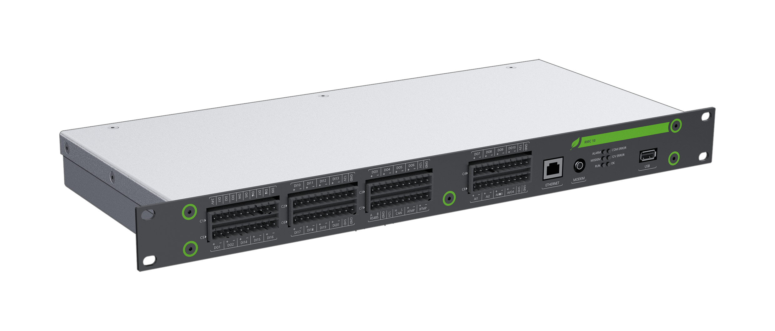
Figure 3.1. The Clear Blue Techologies RMC controller unit
The Converter Unit (see figure 3.2) contains:
- Rectifier up to 3 x 3,5 kW
- Solar converter up to 6 x 2,2 kW
- SCR functionality (replaces standard ATS) for AC power source switching
- Current, voltage, frequency and temperature sensors
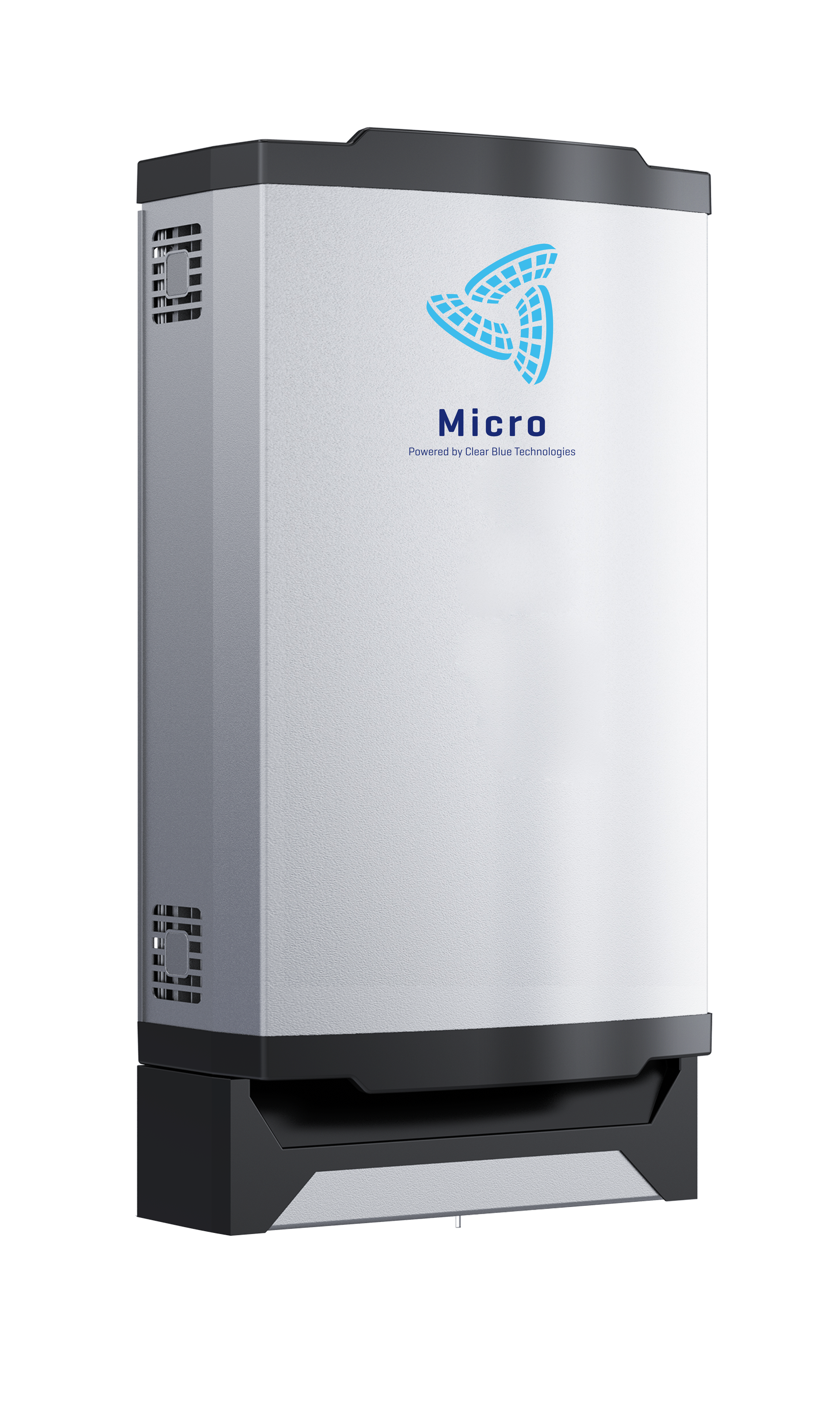
Figure 3.2. A Clear Blue Technologies Micro Converter Unit.
The Power Combiner Unit (see figure 3.3) contains the connection points and MCB breakers for all DC power connections to the RMC, Li-ion battery bank, Converter Units, cabinet fans and customer load. In the standard design, the PCU is equipped to support 2 Converter Units, 4 Tenants and a battery bank of 10 BMUs.
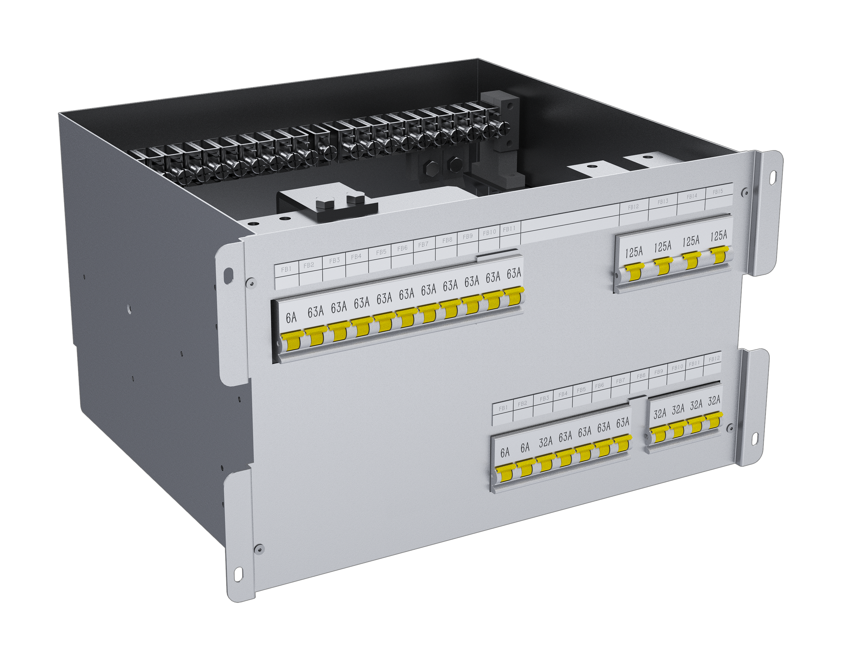
Figure 3.3. The Power Combiner Unit (PCU).
A complete Clear Blue Technologies Micro system setup with all components integrated to a cabinet is shown in figure 3.4.
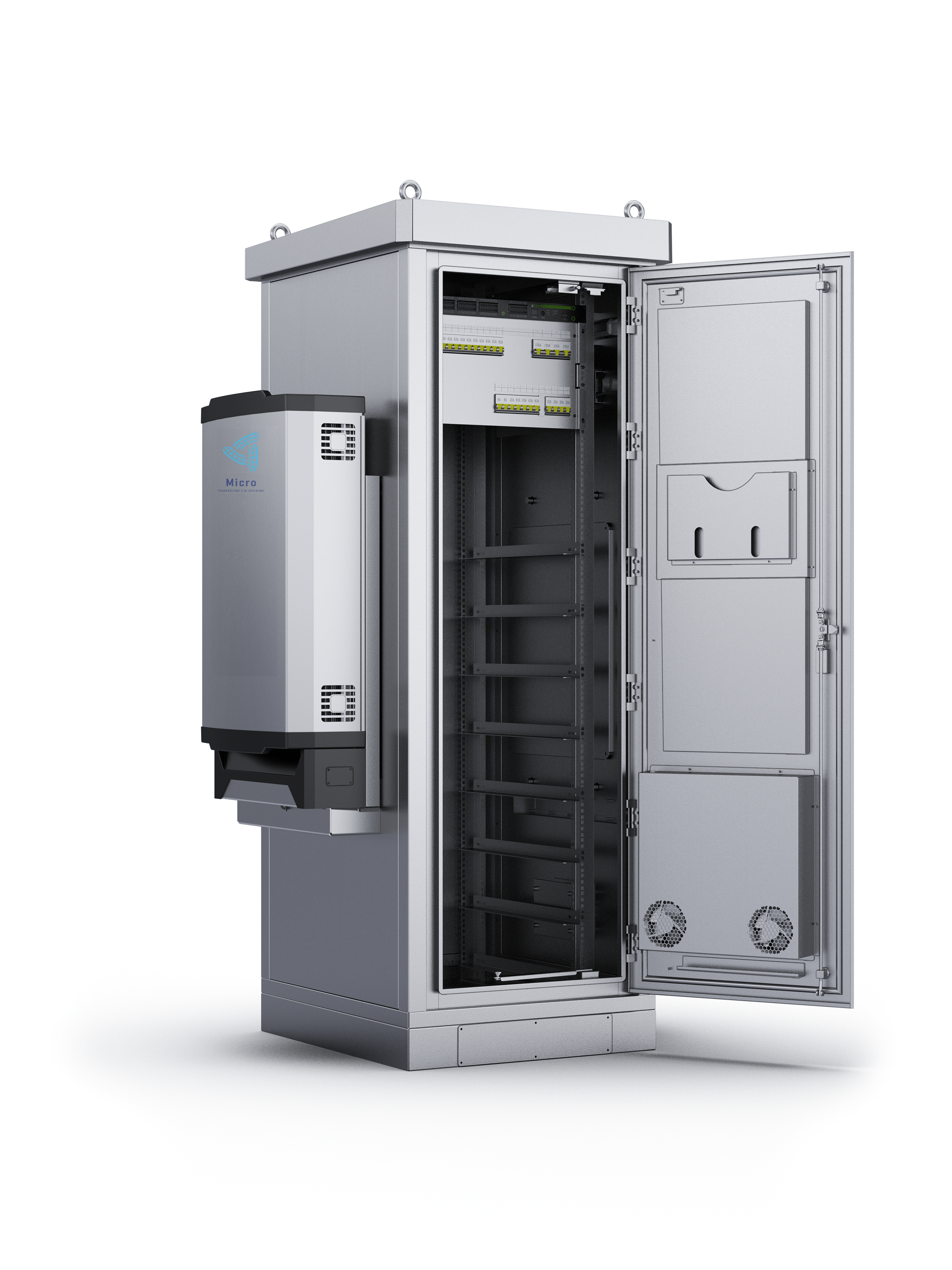
Figure 3.4. Complete Clear Blue Technologies Micro setup with cabinet, Converter Unit, RMC and PCU.