
9 Replace and Repair
9.1 Ambient air temperature sensor
The ambient air temperature sensor consists of a thermistor on a cable. Place the sensor hanging below the Connection Compartment. For more information about 12 V, 24 V and GND see section Connection point 24 V, GND and 12 V.
| Part | Comment | Connection point A | Connection point B |
|---|---|---|---|
| Ambient air temp sensor cable 1 | Not polarity dependent | 12 V | N/A |
| Ambient air temp sensor cable 2 | Not polarity dependent | C8:2 Analogue in 1+ | N/A |
| Resistor 10 k | C8:2 Analogue in 1+ | C8:3 Analogue in 1- | |
| Jumper cable | GND | C8:3 Analogue in 1- |
9.2 Battery temperature sensor
The battery temperature sensor consists of a thermistor on a cable, standard length 5 m. Place the sensor in the battery cabinet in the centre of the battery bank.
| Part | Comment | Connection point |
|---|---|---|
| Battery temp sensor cable 1 | Not polarity dependent | C7:9 |
| Battery temp sensor cable 2 | Not polarity dependent | C7:10 |
9.3 Battery voltage sensor
ℹ️ Note
The sensor resides inside the Main Compartment. The blue and black cables attached to the battery terminals are the sensor probes.
The battery voltage sensor probes connect directly to the battery terminals. They are polarity sensitive, but are protected for reversed polarity. On the negative probe there is a tubular fuse (slow acting, 1 A, 48 V). The probe is connected to the blue internal cables in the Connection Compartment.
9.4 CAN communication and current sensors
For external current measurements, eSite x10 uses complementary LEM current sensors (see figure 9.1). LEM current sensors utilize the CAN protocol for communication with the eSite x10. The CAN cable kit provided by eSite Power Systems is specifically prepared for use with LEM sensors. The white contacts can be used to connect several current sensors. The connection order does not matter.
ℹ️ Note
Each sensor has a fixed, predetermined CAN ID which is printed on the sensor and should be clearly visible. Make sure to do the correct system configurations for each installed sensor in the eSite Web pages. The CAN ID must be unique for each sensor in the system.
The current sensors may be used for battery banks, external solar converters and tenants.
The following CAN IDs are presently configurable:
- 001 (3C1)
- 002 (3C2)
- 003 (3C3)
- 004 (3C4)
- 005 (3C5)
- 006 (3C6)
- 007 (3C7)
- 008 (3C8)
- 009 (3C9)
- 000 (3C0)

For more information about 12 V, 24 V and GND see section Connection point 24 V, GND and 12 V.
| Part | Comment | Connection point |
|---|---|---|
| CAN cable | Orange – White | C7:5 CAN–H |
| CAN cable | Orange | C7:6 CAN–L |
| CAN cable | Brown | GND |
| CAN cable | Brown – White | 12 V |
9.5 Fuel sensors
The fuel sensor must be supplied with 24 V and 0‒10 V output. The colour coding below is valid for fuel sensors supplied by eSite Power Systems. For more information about 12 V, 24 V and GND see section Connection point 24 V, GND and 12 V.
Fuel sensor 1
| Part | Comment | Connection point A | Connection point B |
|---|---|---|---|
| Fuel Sensor cable | Red, 24 V | +24 V | |
| Fuel Sensor cable | Green, GND | GND | |
| Fuel Sensor cable | Yellow, signal | C8:5 | |
| Jumper cable | C8:4 | GND 24 V |
Fuel sensor 2
| Part | Comment | Connection point A | Connection point B |
|---|---|---|---|
| Fuel Sensor cable | Red, 24 V | +24 V | |
| Fuel Sensor cable | Green, GND | GND | |
| Fuel Sensor cable | Yellow, signal | C8:6 | |
| Jumper cable | C8:7 | GND 24 V |
9.6 Connection compartment LEDs
For more information about 12 V, 24 V and GND see section Connection point 24 V, GND and 12 V.
| Part | Comment | Connection point A | Connection point B |
|---|---|---|---|
| Jumper cable | – | 12 V | C2:6 |
| Green LED | – | C2:7 | X1 on LED |
| Green LED | – | GND | X2 on LED |
| Jumper cable | 12 V | C2:6 | C2:8 |
| Red LED | – | C2:9 | X1 on LED |
| Red LED | – | C6:10 | GND |
9.7 Genset start battery charger
The genset start battery charger is a DC to DC converter with a fuse of 7.5 A, 48 V. It is powered from LP. Output voltage shall be 13.5 V.
| Part | Comment | Connection point A | Connection point B |
|---|---|---|---|
| DCDC 48/12 | Input 1 on DC to DC converter | Main earth bar | |
| DCDC 48/12 | Fuse (7.5 A) on line | Input 2 on DC to DC converter | Low prio busbar |
| DCDC 48/12 | Input 3 on DC to DC converter | Main earth bar |
9.8 Door switch
Default configuration: 24 V = no alarm, 0 V = alarm. For more information about 12 V, 24 V and GND see section Connection point 24 V, GND and 12 V.
| Part | Comment | Connection point A | Connection point B |
|---|---|---|---|
| Door switch | 24 V | Door switch | |
| Door switch | C2:5 Connection Compartment lid | Door switch |
9.9 Connection point 24 V, GND and 12 V
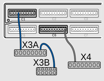
All 24 V, GND and 12 V connection points on the I/O terminals, according to I/O list, can be used, but its preferred to use the terminal when available.
| Connection Compartment serial number | 24 V | GND | 12 V |
|---|---|---|---|
| Serial number equal to and below 065 | 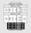 X3 below the Bypass breakers | Use any available GND 24 on the I/O terminals. | Only the 12 V on the I/O terminals are available. |
Serial number equal to and above 066
| X3A, X3B | X4 | Only the 12 V on the I/O terminals are available. |
9.10 Replacement of Main compartment
9.10.1 When to replace the Main Compartment
Replace the Main Compartment only if suggested by an alarm or by a suggested action in the troubleshooting chapter. All prior corrective actions must be tried and failed.
Fill in a replacement report for each unit before it is replaced. Send the report to eSite Power Systems. A Return Material Authorization (RMA) number is provided from eSite Power Systems. The RMA number must be clearly labelled on the returning box to eSite Power Systems for the warranty to be processed.
9.10.2 Overview of the Main Compartment

A Main Compartment guides
B Lower Main
C Mounting frame
9.10.3 Tools list for replacement
For replacement of eSite x10 Main Compartment and for troubleshooting during the replacement use the tools listed below.

A Torx T10 and T20
B Ring spanner 8 mm and 17 mm
C Screwdriver 2.4 mm and 5 mm (common blade)
D Screwdriver PZ2 (Pozidriv)
E Gloves
F Wire cutter
G Network cable
H Laptop
I Goggles
J Pen
K Camera / smartphone
L Socket wrench 13 mm and 16 mm
M Multimeter
N Ampere clamp
9.10.4 How to lift the Main Compartment
⚠️ Warning
The Main Compartment must not be lifted by one person alone.
Before you lift the Main Compartment you must:
- know the weight of the Main Compartment (70 kg).
- make sure the area is clear of obstruction.
- make sure there are no wet or slippery surfaces in the area.
When you lift the Main Compartment, do as follows:
- Stand as close to the box as possible.
- Make sure you are steady on your feet and keep a good balance.
- Keep your back straight and use your legs and hips to lower yourself down to the box.
- Get a firm hold of the Main Compartment with your hands.
- Lift slowly by extending your legs with your back straight.

9.10.5 Disconnect and pack the Main Compartment
⚠️ Warning
Do not touch the pins on the upper part of the Connection Compartment. Once the Main Compartment is removed, there is live power in the pins. There is a risk for electrical shock.
⚠️ Warning
During operation, the Main Compartment may become very hot. Ensure that it has cooled down sufficiently before undocking it. There is a burn hazard.
ℹ️ Note
Have all required information to perform the site commission on the new Main Compartment available. If eSite Web is accessible on the used Main Compartment, a backup of configuration can be taken to upload to the new Main Compartment.
ℹ️ Note
Removing/inserting the SIM card may be easier to do when the Main Compartment is undocked.
ℹ️ Note
Fill in the Main Compartment replacement report before you begin disconnecting and packing the Main Compartment.
| Steps | |
|---|---|
 | 1) Switch off the genset breaker. |
 | 5) Disconnect the I/O terminals. |
 | 6) Remove the GSM antenna. |
 | 8) Remove the three screws and remove the black plastic lid from the Lower Main. Use a torx T10. |
 | 10) Slide the SIM card holder to the right and lift the left side. |
 | 15) Pull out the latch and lift the Main Compartment. Let it slide up and out of the slots. |
 | 19) Put the used Main Compartment in the transportation box in which the new Main Compartment is delivered. One styrofoam is for the top of the Main Compartment and one styrofoam is for the bottom. Ensure they are fitted correctly when lowering the used Main Compartment into the package. Pack the Main Compartment properly to prevent any further damages. |
9.10.6 Dock the Main Compartment
🚨 Caution
When out of the box the lower part of the Main Compartment must not touch soil or grass.
🚨 Caution
The two Main Compartment guides must slide into the slots for the Main Compartment to be correctly installed.
| Steps | |
|---|---|
 | 1) Pry the locks open on the transportation box for the Main Compartment. |
Make sure that the Main Compartment is tight together with the Connection Compartment to prevent problems because of distance between the compartments. The dark grey area on the Main Compartment must completely cover the dark grey area of the Connection Compartment.
9.10.7 Connect the Lower Main

A I/O screw terminals
B LED 1–3
C Ethernet socket
D Antenna socket 1 – GSM antenna
E Antenna socket 2 – Wi-Fi antenna (RSY model)
F 1 x USB port (2 x USB for RSY model) used for software updates (not to be used for mobile phone charging)
G SIM card holder
9.10.8 Install the SIM card
🚨 Caution
Be careful when installing the SIM card. The holder is easily damaged.
ℹ️ Note
Before installing the SIM card, please make sure that the SIM card is working and that it has data. The SIM card must not have a PIN code.
| Steps | |
|---|---|
 | 1) Remove the three screws and remove the black plastic lid from the Lower Main. Use a torx T10. |
 | 3) Slide the SIM card holder to the right and lift the left side. |
9.10.9 Connect the I/O terminals
The sensors and antennas are connected to the Lower Main. When the Main Compartment is docked, the Lower Main is accessed through the Connection Compartment.
The I/O screw terminals are categorized as TNV-2 circuit according to IEC 60950-1.
| Steps | |
|---|---|
 | 1) Install the 8 I/O screw terminals on to the Lower Main. Install them according to the labels, C1, C2, C3, C4, C5, C6, C7 and C8. |
 | 2) Connect the GSM antenna to the Ant 1 socket on the Lower Main. |
Copyright © 2021 eSite Power Systems AB