
3 Main Compartment
3.1 Introduction
The Main Compartment contains all central parts and functions of eSite x10 such as rectifiers, solar converters, control unit, sensors and IOs, and modem. It is sealed and tamper-proof, which prevents users from opening the unit and unintentionally damage it. It also protects the users from dangerous voltage.
eSite x10 can use grid and genset to provide power to the customer load. Solar panels can also be used with eSite x10.
The Main Compartment is available in different variants. It can be equipped with rectifiers with soft-switching ATS functionality and solar converters, or it can be without solar converters. Expansion variants can be used to increase rectifier capacity.
⚠️ Warning
Do not open the Main Compartment. Opening the Main Compartment can result in serious injury. The Main Compartment does not contain any user serviceable parts.
🚨 Caution
The Main Compartment is designed to be connected to the Connection Compartment only, unless a written statement from eSite Power Systems lists additional connectivity devices. The use of third-party connection devices requires explicit consent and approval by eSite Power Systems. The entire Connection Compartment and the power connectivity is subject to regulatory control by eSite Power Systems.
🚨 Caution
In case of failure or performance deviations, the Main Compartment must be returned to eSite Power Systems along with a replacement report. A Return Material Authorization (RMA) number is provided from eSite Power Systems. The RMA number must be clearly labelled on the returning box to eSite Power Systems for the warranty issue to be processed.
3.2 Rectifiers
3.2.1 Silicon Controlled Rectifier (SCR) with ATS functionality
The Main Compartment converts the AC supply via three rectifiers into -48V DC. The rectifiers provide 3.5 kW per unit, total 10.5 kW. The inputs from the AC sources are continuously measured to ensure that the most efficient AC source is used. The switch between the connected gensets/grid is automatic.
The eSite x10 patented Silicon Controlled Rectifier (SCR) is designed to improve the performance of the system compared to a traditional Automatic Transfer Switch (ATS). Both an ATS and SCR allows switching between two AC sources, but while the ATS is based on mechanical switching, the SCR uses power semiconductors.
Advantages of SCR
- No moving parts that are sensitive to dust and wear.
- Unlimited number of cycles.
- Automatic control of the AC input with adaptable thresholds remotely through eSite Tools.
- Overvoltage protection. Input with overvoltage condition is immediately disconnected to protect the rectifier and eSite x10 from wiring faults.
- No separate voltage supply is required for SCR to operate.
- No manual by-pass switch is required. SCR is incorporated into the eSite x10 and the power lines run separately.
- Individual control of each AC phase. One SCR per rectifier.
3.2.2 Electrical protection
eSite x10 is equipped with extensive high voltage protection. It withstands electrical hazards such as lightning induced voltage spikes, malfunctioning gensets, or poor grid stability. It is not only prevented from causing damage, but all incoming surge energy is converted into useful energy. The protection is automatic with no need for a manual reset.
Figure 3.1 illustrates electrical surges from the grid and/or genset(s) divided into different areas.
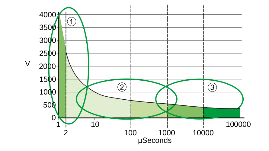
Figure 3.1.
- Surge pulses usually caused by lightning. Gas discharge tubes are used in the input AC stages together with varistors and capacitors to dampen the pulse to a manageable level.
- Combination of surge pulses from lightning and voltage spikes from the grid due to inductive switching, poor grid stability, and long transmission lines. The spikes can also derive from gensets with malfunctioning Automatic Voltage Control (AVR). Carefully selected components in the SCR absorbs these pulses without breaking the affected components.
- Long lasting voltage increases from the grid and gensets. Increases can be caused by incorrect wiring resulting in 400 V AC instead of 240 V AC. SCR disconnects the voltage source. The voltage is constantly monitored and when in the allowed range, the voltage source is automatically reconnected.
Figure 3.2 shows surge areas in which the rectifier system in eSite x10 are protected. The rectifier system on eSite x10 is protected from disturbances located in all three areas (A, B, and C).

The only regulatory demand for rectifiers is to be protected from electrical surges in area A. With additional Surge Protection Device (SPD) area B can also be protected but region C remains unprotected.
3.2.3 Rectifier efficiency and derating
The current limit is 19 A for each rectifier, due to that the power output will be reduced at lower AC voltages. The graph below shows the power derating vs input voltage below 45 °C.

The peak rectifier efficiency is at 95 %. The overall power system peak performance is at 94 %. The graph below shows the rectifier efficiency measured in watt per rectifier.

3.3 Solar converters
A Main Compartment with solar converters is available.
Power from the solar panels is converted via three solar converters into -48V DC, each converter provides 2 kW, total 6 kW. The solar converters consist of a non-isolated step down DC/DC converter and is protected against ground faults, reversed polarity, and over voltages.
Each converter has high performance Maximum Power Point Tracker (MPPT) algorithm that continuously maximizes power output from the panels. The solar converters are tightly integrated with the rectifiers and the battery charge strategies to always optimize the use of solar power.
3.4 Convection cooling
eSite x10 is cooled using passive convection cooling. The solution is constructed to perform adequate cooling without fans, filters, or moving parts.
| Convection cooling benefits |
|---|
| All electronics are sufficiently cooled. |
| No power is needed for cooling. |
| Minimized maintenance and no moving parts that require repair. |
| Totally silent. |

3.5 External interfaces
All external hardware interfaces on the eSite x10 are located on the Lower Main, which is part of the Main Compartment but accessed through the Connection Compartment.
Access to site for configuration, site information, and troubleshooting can be done remotely or locally. Locally, the site can be accessed via Wi-Fi or LAN using smartphone or laptop. Remotely, this can be done using the built in modem and eSite Tools. This requires an installed SIM card for mobile network communication. SIM card is not included in the product.
An overview of the Lower Main is shown in figure 3.6, with important parts marked and identified as follows.

A I/O screw terminals
B LED 1–3
C Ethernet socket
D Antenna socket 1 – GSM antenna
E Antenna socket 2 – Wi-Fi antenna
F 1 USB port used for software updates (not used for mobile phone charging)
G SIM card holder
3.6 Technical specifications
| AC Input | |
|---|---|
| Nominal AC input | 230–250 V AC |
| Permitted AC input range | 85–300 V AC |
| Frequency | 45–65 Hz |
| Input current | 3 x 19 A |
| Power factor | >0.99 |
| THD | <5 % at 230 V AC, 100 % load |
| Input voltage derating | Linear derating for each phase, 3500 W @ 190 V AC, 1500W @ 85V |
| Protection | Varistor transient protection of all phases towards neutral. Varistor and GDT transient protection towards protective earth. Solid state transfer switch for long duration over voltages. |
| DC Output | |
|---|---|
| Operational range | -42 – -58 V DC |
| Rectifier capacity | 3 x 3500 W |
| Output power | 10500 W |
| Current | 195 A @ 54 V |
| Max current | 235 A |
Output Power Derating by Ambient Temperature, | Continuous power at 45 ⁰C: 9750 W |
Output Power Derating by Ambient Temperature, Cyclic Operation (230 VAC). | Full power at 45 ⁰C for 65 min, then derating to 9750 W |
| Rectifier peak efficiency | 95 %* |
| DC power system efficiency | 94 % |
| DC power port for Low Priority Load | 7000 W |
| DC power port for High Priority Load | 3000 W |
*The value includes an integrated static transfer switch.
| Solar Converter | |
|---|---|
| Nominal input voltage | 125 V DC |
| Permitted input voltage range | 50–150 V DC |
| Maximum input current | 3 x 20 A |
| Power conversion capacity | 6,6 kW |
| Power conversion peak efficiency | > 96.5 % |
| Environmental | |
|---|---|
| Nominal Temperature | - 20 – + 45 °C |
| Operating Temperature | - 20 – + 50 °C |
| Storage Temperature | - 40 – + 70 °C |
| Relative Humidity | 0–99 % |
| Cooling | Passive Convection Cooling |
| IP Code | Main Compartment IP65 |
| EMC | ETSI EN 300 386 V1.6.1 |
| Safety | IEC/EN 60950-1:2005+A1+A11+A12+A |
| Environmental standards | ETSI 300 019-1-2 Class 2.3 Public Transportation |
| MTBF | >350 000 h (@T ambient 25 °C) according to Siemens SN29500 |
| Communication ports | |
|---|---|
| I/O | 4 Digital outputs; 8 Digital inputs; 4 Analog inputs |
| External Bus | CAN; RS485; Ethernet |
| WLAN | Wi-Fi access point as service interface; SMA Connector |
| Radio modem | UMTS/HSPA: 850/900/1900/2100 MHz |
| Service port | Ethernet |
| Isolation | 3.0 kV AC mains – Earth |
The sensor configuration on site depends on the selected options and settings. All the I/O screw terminals are protected against reversed polarity and short circuits.