
4 eSite Web
4.1 Overview
The eSite Web interface is accessed on site via a laptop or a smartphone using Wifi or LAN cable, see Site Commissioning on how to connect to Wifi. The interface provides the user with an overview of the status of the eSite Modular system and active alarms. It also offers possibilities to configure the system, update controller softwares and download backup data.
From the front page, which displays an overview of the most important system information, tabs with more detailed information about various system parts are accessed. An example of the view on the eSite Web front page is shown in Figure 4.1. Click the labels on the menu bar to access the detailed information sections and to configure the system.
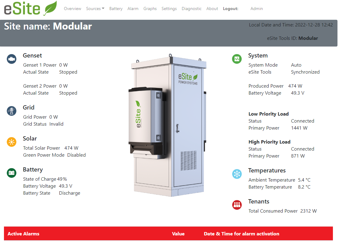
Figure 4.1. eSite Web front page with system overview.
The eSite Web front page contains the following information about the specific eSite Modular system.
| Information shown | Possible values/input | Comment |
|---|---|---|
| Site name | Text input from configuration. | Usually the town or area where the eSite Modular system is located. |
| Local date and time | Year - Month - Day Hour : min | Present local date and time. |
| eSite Tools ID | Text input from configuration. | Identifies this particular eSite Modular system in eSite Tools. |
| System mode | Auto / Auto Full Charge / Manual / Safe mode / UPS mode / Registration mode | Indicates in which mode the system is currently operating. |
| eSite Tools server connection | Not configured / No connection / Synchronized | Indicates the status of the connection to eSite Tools server. |
| AC Source/Solar status | Power (W), and present state of the power source. | For more information, see sections "Genset information", "Grid information" and "Solar information". |
| Battery status | State of charge (%), voltage (V) and battery state. | For more information, see section "Battery information". |
| LP/HP Load status | Connection status and present consumed power (W) | Displays the connection status and size of the low proiority and high priority parts of the customer load. |
| Temperatures | Ambient temperature (°C) Battery temperature (°C) | Displays the present temperatures of the ambient air outside the battery cabinet and the temperature inside the battery cabinet. |
| Tenants | Total consumed power (W) and Tenant 1-10 power (W) | Displays the total consumed power by the customer load and any individually measured tenant powers. |
4.2 User Levels
eSite Web supports two user levels, 'Operator' and 'Admin'. Each user requires a unique user name and a password. Default passwords are provided by eSite Power Systems. Passwords may only be changed by an 'Admin' user.
| User level | Access |
|---|---|
| Operator | View data and alarms (read only). |
| Admin | View data and alarms. Configure the system. Update system software and download backup data. |
4.3 Battery Information
The Battery menu provides the information in the table below. For further information about operating the batteries, please refer to the reference Batteries section.
| Information shown | Possible values | Comment |
|---|---|---|
| Battery type | Type name selected from configuration. | The battery type is shown in the table header. |
| State of Charge (SoC) | % | Shows battery state of charge. 0 % = empty batteries with no energy left. 100 % = fully charged. |
| Battery state | Precharge / Discharge / Charge / Absorb / Equalized / Equilibirum / Fully charged | For more information see Battery states |
| Battery voltage | V | The present battery voltage. |
| Battery temperature | °C | Reads battery temperature from sensor placed in the battery bank. |
| Battery charge current | A | Total current going in and out of the battery bank(s). A negative current indicates discharge and a positive current indicates charge. |
| Battery capacity | Ah | Total battery bank max capacity. Depending on battery configuration this either shows the specified maximum capacity or dynamically estimates the maximum capacity. |
| Charge mode | Normal charge / Full charge / Extended Full Charge / Balancing Full Charge / Safe Mode / Ramp Up / Synchronize | Shows what charge mode that is currently active. |
| Charge request | Not active / Active | When active, eSite requires power to charge the batteries. |
| Cooling Fan status | Off / On / Forced On / Fall back | The Fan can be forced on via command see Configuration pages. Fall back status means that Ambient- and/or Battery-sensor are disconnected. |
| Battery charge strategy | Voltage control / Static SoC / Partial SoC / Li-ion Static / UPS AC Mode | Shows what charge strategy is currently active. The battery charge strategy can be configured, for more information see section Batteries. |
| Voltage Cycle Start | V | Voltage level to trigger charge cycle. |
| Voltage Cycle Stop | V | Voltage level for charge done. |
| Voltage Cycle Stop Current | A | Charge current for charge done. |
| Voltage Cycle Stop Time | sec | Charge time after reaching stop voltage and stop current. |
| Voltage Cycle Full Charge Time / Time Left | sec | Time between full charge cycles and time left until a full charge is triggered. |
| Voltage Cycle Full Charge Energy / Energy Left | kWh | Energy throughput between full charge cycles and throughput left until a full charge is triggered. |
| Static SoC Window start | % | SoC level to start charge. |
| Static SoC Window stop | % | SoC level to stop charge. |
| Static SoC Window Full Charge Time / Time Left | sec | Time between full charge cycles and time left until a full charge is triggered. |
| Static SoC Window Full Charge Energy / Energy Left | kWh | Energy throughput between full charge cycles and throughput left until a full charge is triggered. |
| Partial SoC Window | % | Falling SoC window to start charging. |
| Partial SoC Stop Current | A | Current level for charge done. |
| Partial SoC Stop Voltage | V | Voltage level to stop charging. |
| Partial SoC Stop SoC | % | Falling SoC window between charge cycles. |
| Partial SoC Full Charge Voltage | V | Lower voltage level to force full charge. |
| Partial SoC Full Charge Time / Time Left | sec | Time between full charge cycles and time left until a full charge is triggered. |
| Partial SoC Full Charge Energy / Energy Left | kWh | Energy throughput between full charge cycles and throughput left until a full charge is triggered. |
| Hybrid Shifting Status | enum | 0=Not active, 1=Active. For more information see section Hybrid Shifting. |
| Peak Load Shifting status | enum | 0=Not active, 1=Active. For more information see section Peak Load Shifting. |
| BMU data / Status | enum | Invalid / Not installed / No communication / Operational / Not Operational |
| BMU data / SoC | % | State of Charge for each BMU. |
| BMU data / SoH | % | State of Health for each BMU. |
| BMU data / Current | A | Total current going in and out of the battery BMU. A negative current indicates discharge and a positive current indicates charge. |
| BMU data / Max Cell Voltage | V | Maximum Cell Voltage. |
| BMU data / Min Cell Voltage | V | Minimum Cell Voltage. |
| BMU data / Total Voltage | V | Total Voltage of the Module. |
| BMU data / Charge mode | - | Charge mode of the module can be charge or discharge. |
4.4 Genset Information
The eSite Modular system supports operation of up to two (2) gensets connected simultaneously. The configured gensets are visible under the Genset tab. The Genset tab provides the information shown in the table below. For further information about Gensets, read the reference section Genset(s).
| Information shown | Possible values | Comment |
|---|---|---|
| Operational mode | Forced on / All AC sources forced off / Auto | Actual genset operational mode commanded by the eSite RMC. |
| Night Silence mode | Disabled / Inactive / Pre charge / Silent period active / Silent period aborted | If Night Silence mode is active, the genset is inhibited until it leaves night silence or Night Silence is aborted. |
| Genset mode | Ready / Start Request / Warm-up / Ramp Up / Running / Ramp Down / Cool Down / Off | eSite controlled state of the genset(s). A counter shows for how long a mode has been active, for example for Running, or how many seconds that are left, for example for Warmup. |
| Actual state | Stopped / Running | Detected state of the genset. |
| Unexpected genset start | Yes / No | Genset is running without active start command from the eSite RMC. |
| Power request | W | Requested power from the genset, kept at maximum capacity rating. |
| Genset power | W | Produced power from genset. |
| Produced current | A | Produced current from genset. |
| L1 | V (Hz) | Voltage and frequency. |
| L2 | V (Hz) | Voltage and frequency. |
| L3 | V (Hz) | Voltage and frequency. |
| Genset service countdown | h | Time left until genset service. |
| Total genset run hours | h | Runtime since eSite Modular installation. |
| Tank X volume | l | Present volume in tank. |
| Tank X max volume | l | The maximum volume of the tank is configured under the configuration menu Fuel monitoring. |
4.5 Solar Information
Information from all connected solar converters are displayed under the Solar menu. The Solar menu provides the information shown in the table below. For further information about solar arrays, read the reference in section Solar management.
| Information shown | Possible values | Comment |
|---|---|---|
| Total power | W | Total produced power from the solar converters. |
| Total current | A | Total produced output current from the solar converters. |
| Array voltage (Solar x) | V | Voltage of a specific array. |
| Output power (Solar x) | W | Produced power from the array. |
4.6 Grid Information
The Grid tab provides the information shown in the table below. For further information about Grid read the reference in section Grid
| Information shown | Possible values | Comment |
|---|---|---|
| Grid status | Invalid / Inhibited / Partial / Ok | Invalid when no grid power is available, Inhibited if Green Power mode is configured to inhibit grid power, Partial 1 or 2 phases are not available. |
| Grid power | W | Power drawn from grid. |
| Grid current | A | Produced DC current from grid. |
| L1 | V, A, Hz | Phase 1 AC voltage, current and frequency. |
| L2 | V, A, Hz | Phase 2 AC voltage, current and frequency. |
| L3 | V, A, Hz) | Phase 3 AC voltage, current and frequency. |
| Grid fuse | A | Configured size of the maximum rating of the grid fuse (on the AC side) on site. |
4.7 Alarm Information
The Alarm tab displays any active alarms on site. For a full list of alarms with descriptions and recommended actions, see section Alarm list. The eSite Web Alarm menu provides information about Active alarms and the time of activation for each alarm.
4.8 Graphs
The eSite Web 'Graphs' page provides the graphs given in the table below. Enter the number of days to display in the graphs and click Submit. The default graphs present data for a period of one day.
| Information shown | Comment |
|---|---|
| Graph – Temperatures | Shows Battery and Ambient temperatures for the selected amount of days. |
| Graph – Power | Shows consumed power for the installed Genset 1–2, Grid and Solar power sources for the selected amount of days. |
| Graph – Grid | Shows Grid voltage and current for the selected amount of days. |
| Graph – Genset 1–2 | Shows genset voltage and current for the selected amount of days. |
| Graph – Battery | Shows System voltage, Battery voltage, state of charge and charge current for the selected amount of days. |
| Graph – Tank Volume | Shows tank volume for the selected amount of days. |
The graphs show plots of commonly used system data for a selected period of time in order to facilitate on-site troubleshooting and interpreting alarms. The example in Figure 4.2 shows the temperature data for a period of ten (10) days.
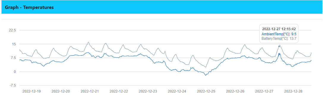
Figure 4.2. Temperature plot over a 10-day period under the 'Graphs' tab.
4.9 About
The About menu provides the information shown in the table below.
| Information shown | Comment |
|---|---|
| Software Versions | – Main controller SW Version -- Linux Version-- Application Software |
| Main Controller Information | – System CPU Temperature -- System Uptime -- MAC address -- IP address |
| HW Info | – RMC serial number -- Unit serial number(s) -- Modem signal strength |
| System Information | -- Commissioning date -- Installed options -- Information about used open source software components |
If a modem is installed , the modem signal strength is displayed as an RSSI classification as follows: 0-10 (Poor), 11-14 (OK), 15-19 (Good), 20-30 (Excellent). If there is an error with the signal, it is shown under this menu.
4.10 Settings
Under the 'Settings' tab, all user settings required for the eSite Modular system and its associated systems are managed. Current settings and values are visible in the column 'Current value'. To update settings and values, enter the new information in the 'Set' column and click 'Save' to confirm the update. The 'Save' button must be clicked for each configuration. The 'Settings' tab is divided into subsections according to the shortcut table below (please click to find relevant configuration parameters) and Figure 4.3.
4.10.1 Settings content
Site commissioning
ℹ️ Note
Some settings are optional and will not be available if the associated option is not installed.
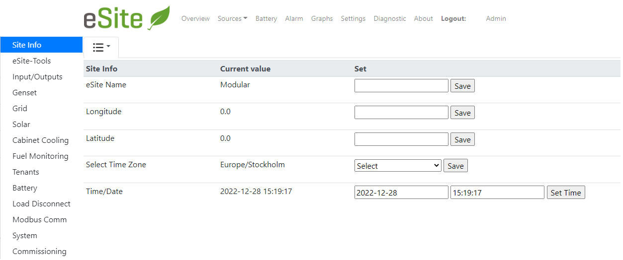
Figure 4.3. Example view of the eSite Web 'Settings' tab.
4.10.2 Site Info
In this section, the user may set the name, location and time of the eSite Modular system.
| Configuration | Default | Option/range | Comment |
|---|---|---|---|
| eSite name | Not Commissioned | - | Name of the site. |
| Longitude | 0.0 | Longitude range -180 to 180 | Enter as decimal degrees. Use format (-)xx(x).xxx(xx). |
| Latitude | 0.0 | Latitude range 90 to 90 | Enter as decimal degrees. Use format (-)xx(x).xxx(xx). |
| Select time zone | Africa /Libreville | N/A | Select correct time zone from the drop down list. |
| Time/Date | N/A | Year - Month - Day Hour : min : sec | The last known local time is automatically used. |
4.10.3 eSite Tools
In this section, parameters for connecting the eSite RMC to a specific eSite Tools server are set.
| Configuration | Default | Option/range | Comment |
|---|---|---|---|
| eSite Tools ID | Not Commissioned | – | Must be unique for each site. Used to reference the site by eSite Tools server. |
| eSite Tools server IP | 0.0.0.0 | – | IP address to eSite Tools server. Provided by eSite Power Systems |
| eSite Event time | 20 sec | – | The time interval for event synchronization between the eSite RMC and eSite Tools. |
| eSite Data update time | 600 sec | – | The time interval for regular data synchronization between the eSite RMC and eSite Tools. |
| IP number to NTP server | pool.ntp.org | – | Retrieves correct time using network Time Protocol (NTP). |
| Enable eSite Tools server time | Off | Off / On | Use server time locally on site. The server time can differ from local site if the server is placed in another time zone. |
| Restart eSite Tools agent | – | – | Restarts eSite Tools agent. After a restart it directly tries to establish a connection to the server. |
| Start eSite Tools communication test | - | - | This will start the communications test to eSite Tools. A log file is created and will be included in the backup archive, goto 'System' menu to backup data. The test can take up to 75 seconds. |
4.10.4 Inputs/Outputs
Use this configuration menu when updating the I/O settings. For more information about I/O see I/O screw terminals where the connection is made.
4.10.4.1 Digital Inputs
The eSite RMC front interface includes 20 Digital Input relay ports with configurable functionality, primarily used for triggering various events when the connected input relay has tripped. The specific functionality of each Digital Input port is configurable from here.
| Configuration | Default | Option/range | Comment |
|---|---|---|---|
| Source A | AC grid | No Source / AC grid / AC genset 1 | Type of AC source connected to AC input A. |
| Source B | No source | No Source / AC grid / AC genset 2 | Type of AC source connected to AC input B. |
| Digital Input 1–20 | Digital input | Digital input / Surge protection / Battery door / MCB Battery bank/ Genset 1–2 Alarm 1–3 | Configures the digital input port to its corresponding relay connection. If set to 'Digital Input', external customer alarms are triggered as Digital Input events. Ports also supports external surge protection alarm, battery door open alarm, battery MCB tripped alarm (forces the system into Safe Mode) and external Genset alarms. |
| Digital Input 1–20 State | Not used | Not used / Normally closed / Normally closed | State configuration of the Digital Input ports depending on relay type. |
4.10.4.2 Analogue Inputs
The eSite RMC front interface includes 4 Analogue Input ports with configurable functionality, that currently supports use of 0-10 V fuel sensors for fuel monitoring. The specific functionality of each Analogue Input port is configurable from here.
| Configuration | Default | Option/range | Comment |
|---|---|---|---|
| Analogue Input 1 | Fuel Sensor Tank 1 | Not Used / Fuel Sensor Tank 1 / Fuel Sensor Tank 2 | Configuration of Analogue Input port functionality. |
| Analogue Input 2 | Fuel Sensor Tank 2 | Not Used / Fuel Sensor Tank 1 / Fuel Sensor Tank 2 | Configuration of Analogue Input port functionality. |
| Analogue Input 3 | Not Used | Not Used / Fuel Sensor Tank 1 / Fuel Sensor Tank 2 | Configuration of Analogue Input port functionality. |
| Analogue Input 4 | Not Used | Not Used / Fuel Sensor Tank 1 / Fuel Sensor Tank 2 | Configuration of Analogue Input port functionality. |
4.10.4.3 Digital Outputs
The eSite RMC front interface includes 10 Digital output ports with configurable functionality. Currently supported functions for Digital Output ports are Genset start commands and start/stop of the Cabinet Cooling equipment. The specific functionality of each Digital Output port is configurable from here.
| Configuration | Default | Option/range | Comment |
|---|---|---|---|
| Digital Output 1 | Genset 1 start cmd | Genset 1 start cmd / Genset 2 start cmd / Cabinet Cooling | Primarily used for Genset 1 start |
| Digital Output 2 | Not used | Genset 1 start cmd / Genset 2 start cmd / Cabinet Cooling | Primarily used for Genset 2 start |
| Digital Output 3 | Cabinet Cooling | Genset 1 start cmd / Genset 2 start cmd / Cabinet Cooling | Primarily used for Cabinet Cooling. |
| Digital Output 4 | Not used | Genset 1 start cmd / Genset 2 start cmd / Cabinet Cooling | Configuration of Digital Out port functionality. |
| Digital Output 5 | Not used | Genset 1 start cmd / Genset 2 start cmd / Cabinet Cooling | Configuration of Digital Out port functionality. |
| Digital Output 6 | Not used | Genset 1 start cmd / Genset 2 start cmd / Cabinet Cooling | Configuration of Digital Out port functionality. |
| Digital Output 7 | Not used | Genset 1 start cmd / Genset 2 start cmd / Cabinet Cooling | Configuration of Digital Out port functionality. |
| Digital Output 8 | Not used | Genset 1 start cmd / Genset 2 start cmd / Cabinet Cooling | Configuration of Digital Out port functionality. |
| Digital Output 9 | Not used | Genset 1 start cmd / Genset 2 start cmd / Cabinet Cooling | Configuration of Digital Out port functionality. |
| Digital Output 10 | Not used | Genset 1 start cmd / Genset 2 start cmd / Cabinet Cooling | Configuration of Digital Out port functionality. |
| Digital Output 1-10 State | Normally open | Normally closed / Normally open | Function of the digital out relay. |
4.10.4.4 Temperature Sensor Settings
From here, it is possible to individually configure the parameters of the Steinhart equation for thyristor temperature conversion for each temperature sensor.
| Configuration | Default | Option/range | Comment |
|---|---|---|---|
| Battery temp sensor Beta | 3977 K | 0-1000 K | Configuration of Beta constant for Steinhart equation. |
| Battery temp sensor R0 | 10000 Ohm | 0-15000 Ohm | Configuration of temp sensor reference resistance. |
| Ambient temp sensor Beta | 3977 K | 0-1000 K | Configuration of Beta constant for Steinhart equation. |
| Ambient temp sensor R0 | 10000 Ohm | 0-15000 Ohm | Configuration of temp sensor reference resistance. |
4.10.5 Genset
In this section, the genset settings can be updated. All gensets connected to the eSite Modular system are visible here, labelled Genset 1 and Genset 2. Click the respective genset name to configure.
This section is also used to update the Night Silence and UPS mode settings.
| Configuration | Default | Option/range | Comment |
|---|---|---|---|
| Genset start alarm delay time | 300 sec | 1-9999 s | Genset Failed to Start/Stop Alarms are triggered when the respective alarms conditions are met for this amount of time. Setting this time to a low value in a dual genset system will result in a quicker genset start. Recommended in UPS mode. |
| Enable Exercise Run | Off | Off / On | Enable the genset exercise run functionality. |
| Interval between exercise runs | 360 hours | 0 – 9999 h | Minimum interval between genset exercise run starts. |
| Genset exercise run duration | 1800 sec | 0 – 9999 s | Genset exercise run time. |
| Night silence enable | Off | Off / On | Enables Night Silence mode. |
| Start time | 20:00 | 00:00 – 23:59 | Start time for silent period. The batteries are pre-charged before this time. |
| Stop time | 08:00 | 00:00 – 23:59 | Stop time for silent period. The genset is allowed to start. |
| Min voltage level | 46.8 V | 0 – 60 V | If the battery voltage falls below this value, the genset is allowed to start and the silence period ends. Only applicable if stop on charge request is disabled. |
| Min SoC level | 0 | 0 – 100 % | If the SoC level falls below this value, the genset is allowed to start and the silence period ends. Only applicable if stop on charge request is disabled. |
| Min Capacity Left | 150 Ah | 0 – 9999 Ah | Night silence mode will end when a charge request becomes active |
| Stop on charge request | On | Off / On | Select if a charge request is allowed to start the genset and end the night silence period. |
| Enable UPS mode | Off | On / Off | Enable UPS functionality. |
| Dual Genset Run Interval | 21600 s (6 h) | 0-99999999 | The time in seconds each genset shall run before switching genset in UPS mode with dual genset setup. |
| Periodic Full Charge Enabled | Disabled | Enabled / Disabled | Enable the periodic full charge option for UPS mode. |
| Full Charge Duration | 12 h | 0 – 9999 h | The time in hours the system shall run the genset on boost voltage level (Full Charge) in UPS mode. |
| Interval between Full Charge | 2160 h (90 days) | 0 – 9999 h | Time between periodic full charge cycles in UPS mode. |
| Full Charge Trigger voltage | 45.5 V | 45 – 60 V | Safety voltage level for triggering a Full Charge cycle in UPS mode. |
| Operational mode | Auto | Auto / Genset Forced on / All AC sources Off | Used to force genset on/off from eSite Web. It is recommended to always leave the operational mode in Auto. |
| Genset rated power | 15 kVA | 0 – 30kVA | Rated power of the genset. The power should not be set higher than the genset capacity. When calculating the genset rated output, only 70% of the total capacity is used. |
| Enable Genset Service alarm | Disabled | Enabled / Disabled | Enable the service time alarm. |
| Genset Service Interval | 250 h | 0 – 9999 h | Time interval of Genset run hours between maintenance of the Genset. Specified by manufacturer. |
| Genset Service Alarm Trigger time | 0 h | 0 – 1 000 h | The Genset Service alarm is triggered when this number of run hours is left until service. |
| Genset Alarm 1–3 | No input | No input / Normally closed / Normally open | When tripped an alarm is triggered. Used for alarms coming from the genset using alarm relays. Same configuration can be found under section 'I/O'. |
| Genset service time reset | N/A | Reset function | Resets service time. The service time is presented on the genset page. |
| Genset run time reset | hours | Set/Reset function | Set the genset runtime to a value. |
| Activate Genset control panel communication | Disabled | Enabled / Disabled | Activates genset control panel communication. See modbus communication for more information. |
| Slave ID | 1 | 1 – 255 | The slave ID must match the slave ID setting on the genset panel. |
| Restart modbus communication after changes | – | – | A restart after change of settings. |
AMF Panel Communication
A set of signals can be configured to be read from the genset panel if they are supported from the genset panel. The following settings must be done for each signal according to the genset panel Modbus communication specification. See the Appendix for an installation guide.
| Signal name | All available signals | Select signal to configure |
|---|---|---|
| Function | No_Function / Read_Holding_Registers / Read_Input_Registers | Select the correct function according to genset panel. |
| Register | 0 – 99 999 | The signal register. |
| Type | BOOLEAN / UINT8 / UINT16 / INT16 / UINT32 High word first / INT32 High word first / UINT32 Low word first / INT32 Low word first IEEE–754 | Select the signal type. |
| Scale | No scale, 10, 100, 1000, 3600 | For signal scaling. |
| Bit position | 1 – 16 | Select the bit position. |
4.10.6 Grid
| Configuration | Default | Option/range | Comment |
|---|---|---|---|
| Maximum grid phase current | 19 A | 0 – 19 A | AC Current limitation for the grid fuse of a single phase. |
4.10.7 Solar
| Configuration | Default | Option/range | Comment |
|---|---|---|---|
| Green Power Influx Enabled | Off | On / Off | Enables Green Power mode. |
| Green Power Mode | Load percent | Load Percent / Time Interval | Allows the user to choose between the two available operational modes. |
| Voltage Activation | 49V | 0 – 60 V | Battery voltage required for activation of the green power influx feature. |
| Voltage Deactivation | 47 V | 0 – 60 V | If the battery voltage goes below this value, Green Power mode is deactivated and the AC source must complete it's charge cycle before Green Power mode is reactivated. |
| SoC Level Activation | 60 % | 0 – 100 % | If Green Power mode is inactive due to low SoC, it is activated when the SoC reaches this value. |
| SoC Level Deactivation | 50 % | 0 – 100 % | Green Power mode is deactivated if the SoC level falls below this value. |
| Activation Delay Timer | 60 s | 0 – 3 600 s | Time needed to ensure that solar power is stable and sufficient. |
| Solar Load Deactivation | 70 % | 0 – 200 % | Solar power percentage of customer load required for solar to be considered sufficient. If Green Power mode is active, it is deactivated when the solar power drops below this limit. If Green Power mode is inactive, it is activated when this limit is exceeded and the specific mode requirements are met. |
| Solar Load Activation | 80 % | 0 – 200 % | Solar power percentage of customer load required for Green Power mode deactivate. |
| AC Source Disable Time | 07:00 | 00:00 – 23:59 | Green Power mode is activated, AC sources are disabled. |
| AC Source Enable Time | 16:30 | 00:00 – 23:59 | Green Power mode is deactivated, AC sources are re-enabled. |
| Reset Solar converter | - | - | Commands all Solar converters in the system to reset. |
4.10.8 Cabinet Cooling
Cabinet Cooling can be configured in two different modes, see table below. The digital output relay need to be configured to 'Cabinet Cooling', see I/O Configuration
| Configuration | Default | Option/range | Comment |
|---|---|---|---|
| Cabinet Cooling mode | No Cabinet Cooling | No Cabinet Cooling, Delta Ambient, Battery temp levels | Delta Ambient mode uses temperatures offsets between battery and ambient temp. Battery Temp Level mode use an temperature set value. |
| Fan On Delta mode (°C) | 8°C | 0-100°C | Temperature difference threshold for turning on battery cooling. |
| Fan Off Delta mode (°C) | 2°C | 0-100°C | Temperature difference threshold for turning off battery cooling. |
| Fan On Level mode (°C) | 32°C | 0-100°C | Temperature threshold for turning on battery cooling. |
| Fan Off Level mode (°C) | 25°C | 0-100°C | Temperature threshold for turning off battery cooling. |
| Min Fan Runtime (sec) | 300 | 10000 (sec) | Minimum runtime for battery cooling fan before it can be turned off. |
| Manually start cooling fan | Current output value | Auto, Cooling Fan On | The output value can be: Off, On, Forced On, Fallback (temp sensor in fallback) |
| Enable Poor Cooling alarm | Off | On / Off | The poor cooling alarm can be activated even without the Cabinet Cooling feature being activated. The alarm is triggered by the temperature threshold below |
| Poor Cooling Alarm Temp Delta Threshold | 12 °C | 0-70 °C | Temperature difference threshold between ambient and battery temperature for triggering of Poor Cooling alarm. |
4.10.9 Fuel Monitoring
In this section, the Fuel monitoring settings can be managed. Up to two (2) fuel tanks with dedicated fuel sensors can be installed. The eSite RMC supports different types of fuel sensors. Click on the respective tanks (Tank 1 and Tank 2) to configure their tank and sensor properties. A fuel sensor with an analogue signal output can be connected to an Analogue Input on the I/O screw terminals. The measuring range of the Analogue Input is 0 – 10 V. Note that the eSite RMC can also read fuel data from the genset panel if a fuel sensor is integrated with the genset. See section Genset Management.
| Configuration | Default | Option/range | Comment |
|---|---|---|---|
| Sensor type | No fuel sensor | No fuel sensor / Volt–height / Volt-litre / Lookup volt-litre | All counters for consumption, fillings and losses are reset when no fuel sensor is selected. Volt–height is used for standard sensor with an voltage output corresponding to pressure or height. Volt–litre is used with sensors that have an voltage output corresponding to liters. Lookup volt – litre is used for example on tanks of irregular shape. |
| Tank shape | Rectangular box | No tank / Rectangular box / Standing cylinder / Horizontal cylinder | Shape of the tank. |
| Tank height | 0 mm | 0 – 10 000 mm | Enter the values as accurately as possible. Do not round off numbers. |
| Tank length | 0 mm | 0 – 10 000 mm | Enter the values as accurately as possible. Do not round off numbers. |
| Tank width | 0 mm | 0 – 10 000 mm | Enter the values as accurately as possible. Do not round off numbers. |
| Tank radius | 0 mm | 0 – 10 000 mm | Only available for cylindrical tank types. The radius can be calculated by measuring the circumference and divide by 2π. |
| Sensor max height | 1 884 mm | 0 – 10 000 mm | For pressure sensor the height is calculated as:h = P/(ρg) where P is pressure in Pasqual (Pa).In the fuel sensor datasheet the range can be specified in Pa, Bar mH 2 O etc. Default for g is 9.812 and the density of diesel (rho) is 866 kg/m 3 . The density of diesel can vary. |
| Sensor output volt min | 0.1 V | 0 – 10 V | If a sensor with voltage as output is selected, these settings must be set. |
| Sensor output volt max | 10 V | 0 – 10 V | If a sensor with voltage as output is selected, these settings must be set. |
4.10.10 Tenants
Settings for the individual tenant current measurements are managed from here.
| Configuration | Default | Option/range | Comment |
|---|---|---|---|
| Enable tenant 1 – 10 current sensor | Off | On / Off | If a tenant sensor is installed, set to "On". |
| Configure CAN ID | ID 0-9 | ID 3C0 - 3C9 | Each tenant sensor has to be configured with the correct sensor ID. Use the dropdown list to select the correct CAN ID. |
| Total load high power alarm | 10 000 W | 0 – 21 000 W | Combined power for both LP and HP and for all tenants. Must be active for 10 seconds. Threshold for high load alarm. |
| Tenant 1 – 10 high power alarm | 5 000 W | 0 – 9 500 W | Only active if tenant current sensor is "On". Must be active for 10 seconds. Threshold to trigger high power alarm. |
4.10.11 Battery
In this section, the Battery settings can be managed. For custom battery configuration, see below.
| Configuration | Default | Option/range | Comment |
|---|---|---|---|
| Battery configuration | NONE | – | A battery template must always be selected. Select it from the dropdown list and press the button. Imported battery configurations will be visible at the end of the list. |
| Import battery configuration | – | – | Press the link to import a new battery configuration file. The file must have the extension '.flx' and be created via the 'Export' link or supplied by eSite Power Systems The new configuration will be visible at the end in the dropdown list. For more information on how to save a custom battery configuration file see section System Update. |
| Export battery configuration | – | – | Press link to create new battery configuration file from current battery values. For more information on how to save a custom battery configuration file see section System Update. |
| Battery charge strategy | Voltage cycle | Voltage cycle/Static SOC/Partial SOC | Different strategy will be visible depends on selected battery configuration. Reed section Batteries for more information. |
| Start a full charge cycle | – | – | Manually trigger a full charge cycle. Recommended for new batteries. When started, system mode reports 'Auto Full Charge' and charge mode on battery page reports 'Full Charge'. |
| Start an extended full charge cycle | – | – | Manually trigger an extended full charge cycle. When started, system mode reports 'Auto Full Charge' and charge mode on battery page reports 'Extended Full Charge'. |
| Start Balancing Full Charge cycle | – | – | Manually trigger a Balancing Full Charge cycle for Li-ion batteries. When started, system mode reports Auto Full Charge and charge mode on the battery page reports Balancing Full Charge. |
| Reset number of charge cycles | – | – | Reset number of completed charge cycles (Li-ion batteries only). |
| Enable Periodic Balancing Full Charge | – | – | Enable periodic Balancing Full Charge cycles (Li-ion batteries only). |
| Balancing Full Charge Energy Throughput | – | – | Energy throughput between Balancing Full Charge cycles (Li-ion batteries only). |
| Balancing Full Charge Number of Cycles Interval | – | – | Number of charge cycles between Balancing Full Charge cycles (Li-ion batteries only). |
| Alarm Battery High Temp | °C | See data sheet of battery | Above this level an alarm is triggered |
| Alarm Battery Very High Temp | °C | See data sheet of battery | Above this level an alarm is triggered |
| Alarm Battery Low Voltage | V | 0-60V | Low voltage alarm |
| Alarm Battery Low Voltage Reset | V | 0-60V | Low voltage alarm reset |
| Reset Battery Total Throughput | – | – | Reset Battery Total Throughput |
4.10.11.1 Lead-Acid Battery Parameters
ℹ️ Note
The following battery parameters apply only for installed lead-acid batteries.
| Configuration | Unit | Recommended value | Description |
|---|---|---|---|
| Set new battery configuration name | - | any text > 3 letters | Set any name to the configuration setup, especially when the configuration shall be exported to other sites but not a requirement. |
| Rated Capacity | Ah | See data sheet of battery | Rated of the battery string/BMU |
| Coulomb Efficiency | See data sheet of battery | Coefficient for compensating Ah round trip efficiency during charging. % * 0.01 | |
| Absorb Voltage | V | Genset/Grid boost voltage – 0.5V | Absorb voltage threshold |
| Absorb Time | sec | 300 s | Absorb time(s) |
| Absorb To Charge Voltage | V | Genset/Grid float voltage – 0.5V | Fall back voltage |
| Equalize Current | A | Rated Battery Capacity * 0.03 | Equalize current |
| Equalize Time | sec | 21600 (6h) | Equalize time(s) |
| Fully Charged Current | A | Rated Battery Capacity * 0.03 | Full charge current |
| Fully Charged Time | sec | 60 | Fully charged time(s) |
| Temperature Compensation X0-X3 | °C | X1>X0, X2>X1, X3>X2 | Temperature compensation, X values, must be increasing with the lowest value in X0. |
| Temperature Compensation Y0-Y3 | V | See data sheet of battery | Voltage compensation, Y values |
| Extended Full Charge Time | sec | 64800 (18h) | Extended full charge time(s) |
| Genset Boost Voltage | V | See data sheet of battery. Max 58V | Boost voltage (topping charge with constant voltage level) |
| Genset Float Voltage | V | See data sheet of battery | Float voltage |
| Grid Boost Voltage | V | See data sheet of battery. Max 58V | Boost voltage (topping charge with constant voltage level) |
| Grid Float Voltage | V | See data sheet of battery | Float voltage |
| Solar Boost Voltage | V | See data sheet of battery. Max 58V | Solar boost voltage |
| Solar Float Voltage | V | See data sheet of battery | Solar float voltage |
| Nominal Current | A | Rated Battery Capacity * 0.2 | Nominal battery charge current. VRLA: Total battery block current. |
| Maximum charge current | A | Rated Battery Capacity * 0.2 | Battery charge current. Lithium-Ion: Set current upon total block size. Use current limit information from Li-ion batteries if present on com bus. |
| Safe Mode Current | A | Same as Nominal Current | Used when the system is in an abnormal state |
| Safe Mode Voltage | V | < Float Genset Voltage | Used when the system is in an abnormal state |
| Voltage Control | Unit | Recommended value | Description |
|---|---|---|---|
| Start Voltage | V | See data sheet of battery | Voltage level for charge start. |
| Stop Voltage | V | See data sheet of battery OR Boost Voltage - 1V | Voltage level for charge done. Stop when Voltage and Current are fulfilled. |
| Stop Current | A | See data sheet of battery OR Rated Battery Capacity/100 | Current level for charge done. Stop when Voltage and Current are fulfilled. |
| Stop Time | sec | See data sheet of battery | Charge time(s) after reaching stop voltage/current |
| Full Charge Time | sec | 864000 (10 days) | Time(s) between full charge cycles |
| Full Charge Energy | kWh | Rated Battery Capacity * 1.18 | Energy throughput between full charge cycles |
| Static SOC | Unit | Recommended value | Description |
|---|---|---|---|
| Start SOC | percent | See data sheet of battery | SOC level to start charge |
| Stop SOC | percent | See data sheet of battery | SOC level to stop charge |
| Full Charge Voltage | V | See data sheet of battery | Lower voltage level to force full charge |
| Full Charge Time | sec | 864000 (10 days) | Time(s) between full charge cycles |
| Full Charge Energy | kWh | Battery Capacity * 1.18 | Energy throughput between full charge cycles |
| Partial SOC | Unit | Recommended value | Description |
|---|---|---|---|
| SOC Window | percent | See data sheet of battery | Falling SOC window to start charging |
| Stop Current | A | See data sheet of battery OR Rated Battery Capacity/100 | Current level for charge done. Stop when Voltage and Current are fulfilled. |
| Stop Voltage | V | See data sheet of battery OR Boost Voltage - 1V | Voltage level for charge done. Stop when Voltage and Current are fulfilled. |
| Inhibit Stop Charging | percent | 35 % | Lower SOC level to keep charge request |
| Full Charge Voltage | V | See data sheet of battery | Lower voltage level to force full charge |
| Full Charge Time | sec | 864000 (10 days) | Time(s) between full charge cycles |
| Full Charge Energy | kWh | Rated Battery Capacity * 1.18 | Energy throughput between full charge cycles |
4.10.11.3 Lithium-ion Battery Parameters
ℹ️ Note
The following battery parameters apply only for installed Li-ion batteries.
| Configuration | Unit | Recommended value | Description |
|---|---|---|---|
| Set new battery configuration name | - | any text > 3 letters | Set any name to the configuration setup, especially when the configuration shall be exported to other sites but not a requirement. |
| Rated Capacity | Ah | See data sheet of battery | Rated of the battery string/BMU |
| Coulomb Efficiency | - | See data sheet of battery | Coefficient for compensating Ah round trip efficiency during charging. % * 0.01 |
| Genset Set Voltage | V | See data sheet of battery. | Set voltage level for Li-ion battery operation when using genset power. Charge request active. |
| Genset Float Voltage | V | See data sheet of battery. | Set voltage level for Li-ion battery when using genset power. Charge request inactive. |
| Solar Set Voltage | V | See data sheet of battery. | Set voltage level for Li-ion battery when using solar power. Charge request active. |
| Solar Float Voltage | V | See data sheet of battery. | Set voltage level for Li-ion battery when using solar power. Charge request inactive. |
| Grid Set Voltage | V | See data sheet of battery. | Set voltage level for Li-ion battery when using grid power. Charge request active. |
| Grid Float Voltage | V | See data sheet of battery. | Set voltage level for Li-ion battery when using grid power. Charge request inactive. |
| Enable Battery Synchronization | - | Disabled | Enable battery synchronization at the end of a charge cycle. |
| Battery Synchronization Current | A | 2 A | Battery synchronization charge current limit. |
| Battery Synchronization Time | sec | 300 s | Battery synchronization step duration. |
| Battery Ramp Up Voltage | Volt | 50 V | Battery ramp up start voltage. |
| Battery Ramp Up Time | sec | 1s | Defines the rate of voltage increase during ramp up. 1 Volt per configured time interval |
| Safe Mode Current | A | Same as Nominal Current | Used when the system is in an abnormal state |
| Safe Mode Voltage | V | < Float Genset Voltage | Used when the system is in an abnormal state |
| Enable Hybrid Shifting | - | Disabled/Enabled | Hybrid shifting set a temporary genset stop value. See details in Battery reference section. |
| Set Shifting On time | hh:mm | - | Time setting to activate hybrid shifting. |
| Set Shifting Off time | hh:mm | - | Time setting to deactivate hybrid shifting. |
| Genset stop voltage | V | - | Genset stop Voltage in Hybrid shifting mode. |
| Enable Peak Load Shifting | - | Disabled/Enabled | Peak Load shifting set a temporary grid float value. See details in Battery reference section. |
| Set Shifting On time | hh:mm | - | Time setting to activate peak load shifting. |
| Set Shifting Off time | hh:mm | - | Time setting to deactivate peak load shifting. |
| Grid Float voltage | V | - | Grid Float Voltage in Peak Load shifting mode. |
| BMS settings | Unit | Recommended value | Description |
|---|---|---|---|
| Charge State Current | A | 1A | Battery charge current threshold to be exceeded for the battery to be in Charge state. |
| Discharge State Current | A | -1A | Battery discharge current threshold to fall below for the battery to be in Discharge state. |
| Charge Time | sec | 10s | Duration of charge or discharge current conditions to be valid until battery state changes. |
| Fully charged cut off | A | Rated Battery Capacity * 0.04 | Threshold of battery charge current to fall below for the battery to be considered fully charged.. |
| Fully charged voltage | V | See data sheet of battery | Threshold of battery voltage to be exceeded for the battery to be considered fully charged. |
| Fully charged time delay | sec | 60 s | Duration of the battery fully charged current AND fully charged voltaqe for the battery to be considered fully chaged. |
| Equlibrium Voltage | V | 0.1 V | Limit of voltage increase/decrease rate for the battery to be considered to be in Equilibrium state. |
| Equlibrium Time | sec | 300 s | Duration of low voltage increase/decrease rate for the battery to enter Equilibrium state. |
| Voltage Control | Unit | Recommended value | Description |
|---|---|---|---|
| Start Voltage | V | See data sheet of battery | Voltage level for charge start |
| Stop Voltage | V | See data sheet of battery | Voltage level for charge done. Stop when Voltage and Current are fulfilled. |
| Stop Current | A | See data sheet of battery | Current level for charge done. Stop when Voltage and Current are fulfilled. |
| Stop Time | sec | See data sheet of battery | Charge time(s) after reaching stop voltage/current |
| Static SoC | Unit | Recommended value | Description |
|---|---|---|---|
| Start SoC | percent | See data sheet of battery | SOC level to start charge |
| Stop SoC | percent | See data sheet of battery | SOC level to stop charge |
| Static SoC control options | - | 2 | 1 = Start/stop on average SOC, 2 = Protective SSOC with active comm. Start/stop on min/max BMU SOC, 3 = Balancing SSOC with active comm. Start/stop on min/min BMU SOC. |
| Balancing Full Charge Trigger Voltage | V | 45.5 V | Safety SOC level to trigger Balancing Full Charge |
4.10.12 Load Disconnect
LVD settings are managed from here.
| Low voltage disconnect settings | Unit | Recommended value | Description |
|---|---|---|---|
| Low Prio load disconnect volt | V | 42-60 V | Voltage to disconnect LP, default=45 V |
| Low Prio load disconnect time | sec | – | Time before LP is disconnected after disconnect thresholds are reached, default=300 s |
| Low Prio load reconnect volt | V | 42-60 V | Voltage required to reconnect LP, default=48 V |
| Low Prio load reconnect time | sec | – | Time before LP is reconnected after reconnect thresholds are reached, default=30 s |
| Low Prio load reconnect current | A | 0-200 A | Produced current required to reconnect LP, default=20 A |
| Low Prio load fast reconnect volt | V | 42-60 V | Voltage required for fast reconnect of LP , default=52 V. |
| High Prio load LVD enable | - | Disabled | If enabled, LVD will use separate settings for High Prio load LVD. Disabled, LVD will use the same settings for High Prio load as for Low Prio load. |
| High Prio load disconnect volt | V | 42-60 V | Voltage to disconnect HP, default=43.5 V |
| High Prio load disconnect time sec | sec | – | Time before HP is disconnected after disconnect thresholds are reached, default=5 s |
| High Prio load reconnect voltage | V | 42-60 V | Voltage required to reconnect HP, default=48 V. |
| High Prio load reconnect time sec | sec | – | Time before LP is reconnected after reconnect thresholds are reached, default=5 s |
4.10.13 Modbus Communication
The Modbus communication functionality enables third party systems to communicate with the eSite RMC. In this section, the Modbus settings are configured.
Modbus/RTU RS-485 Settings
| Configuration | Default | Option/range | Comment |
|---|---|---|---|
| Enable communication to Li-ion BMS | OFF | ON / OFF | Set to ON if communication to Li-ion BMS is installed. |
| Installed Li-Ion modules | 0 | 1-16 | Number of installed BMUs, used to set communication alarms and for communication to BMU. |
| Modbus communication protocol | No protocol selected | See Li-ion batteries for supported batteries | Select the Li-ion battery brand communication protocol to be used. |
| Enable communication to Genset1 AMF panel | OFF | ON / OFF | Set to ON if communication to Genset1 is installed. Configuration needed in Genset tab. |
| Enable communication to Genset2 AMF panel | OFF | ON / OFF | Set to ON if communication to Genset2 is installed. Configuration needed in Genset tab. |
| Slave ID | 0 | 1-255 | The slave ID must not be in conflict with any ID on the modbus. |
| Selected Baudrate | 19200 | 9600 / 19200 / 38400 / 57600 / 115200 | Select the desired RS485 Baudrate for Modbus communication. |
| Restart Modbus handler | – | – | Restart modbus handler when changes are made. |
4.10.14 System
In this section, system updates, downloading of backup data and uploading if configuration data can be performed.
| Configuration | Comment |
|---|---|
| Update eSite main controllers | Software updates for main controller, rectifiers and solar controllers. Update images are provided by eSite Power Systems. |
| Backup data (export) | Backup configuration data, custom battery file, modbus config file and log data. |
| Upload configuration data (import) | Upload to this eSite a new battery file or configuration file here. |
| Update eSite options | Update the Option file. The file, which is provided by eSite Power Systems, must match the serial number of the eSite RMC. |
| Reboot System | Command to reboot the system. |
| Shutdown System | Command to shutdown the system. |
| Factory Reset | Command to restore all settings to default and reboot the system. |
| Modem Reset | Command to reset the modem. Should be done after installing a new SIM card. |
| Reset Load switch | Reset pulse for the LVD breakers. |
| Change password | Select a user to change its password. Write the new user password in the text box and press 'Save' |
| Reset passwords | Reset passwords. Select a user and press 'Reset' button. |
| Add IP address/subnet mask | Add an extra ip address to eth0. Use syntax: xxx.xxx.xxx.xxx/nn where x is the IP address and nn is the subnet mask in Linux notation (24 = mask 255.255.255.0). |
| Add IP gateway | Add a gateway to eth0. Use syntax: xxx.xxx.xxx.xxx where x is the IP address to the gateway |
| IP Restore | Press to restore default IP settings |
| Change APN setting | Change the modem access point name (apn) from default (internet). Be patient, it takes 30 seconds to restart the modem with new settings. |
| Commissioning | This is a forward link to the Site Commissioning guide. During Site Commissioning, settings for the eSite Modular system are finalized upon installation. The Site Commissioning makes sure that the eSite Modular system is set up correctly and operates as intended. Moreover, the Site Commissioning guide is where all RE/RSE/SE Converter Units are registered and unregistered. Detection of a connected, unregistered unit automatically starts the Site Commissioning guide. To unregister a registered Converter Unit, please enter the Site Commissioning guide from this menu |