
3 Description of the eSite Modular system
3.1 eSite Modular introduction
The eSite Modular system consists of 1, 2 or 3 hybrid power Converter Units mounted on the exterior of a cabinet supplying a customer load with stable power by combining software-defined hybrid battery control with solar power, intelligent grid power harvesting and/or optimal genset control.
The interior of the cabinet houses the Remote Monitoring and Control (RMC) unit, the Power Combiner Unit (PCU) and the battery bank. Associated systems are connected to the eSite Modular system via connections points inside the cabinet.
The preconfiguration allows for up to 10 tenants with separate load measurements to simultaneously be connected to the eSite Modular system. The site configuration depends on the site prerequisites.
The eSite Modular system can be supplied with AC power from genset and grid and with DC power from solar panels. The supplied power is used to carry the customer load and to charge a battery bank. The AC supply is converted through ACDC rectifiers in the Converter Unit(s) into -48 V DC. The switching between the connected power sources is automatic. The DC supply is converted through DCDC solar converters in the Converter Unit(s) into -48 V DC. The RMC starts and stops the genset automatically based on the state of the battery bank and the associated charge strategy. If solar arrays are part of the configuration, they are always in operation and will supply power when the weather conditions are right.
The Converter Unit contains the rectifiers and/or solar converters. The unit is sealed and tamper-proof, and preconfigured when delivered. The Converter Unit does not contain serviceable parts.
The RMC controller unit includes all major functionality and all connections to the Converter Units. See the Operations manual for more information how to manage the RMC.
⚠️ Warning
Do not open or make modifications to a Converter Unit or the RMC. This is strictly prohibited and can be a threat to life.
🚨 Caution
In case of a serious system failure or performance deviation, the Converter Unit must be sent to the nearest eSite Power Systems approved service centre.
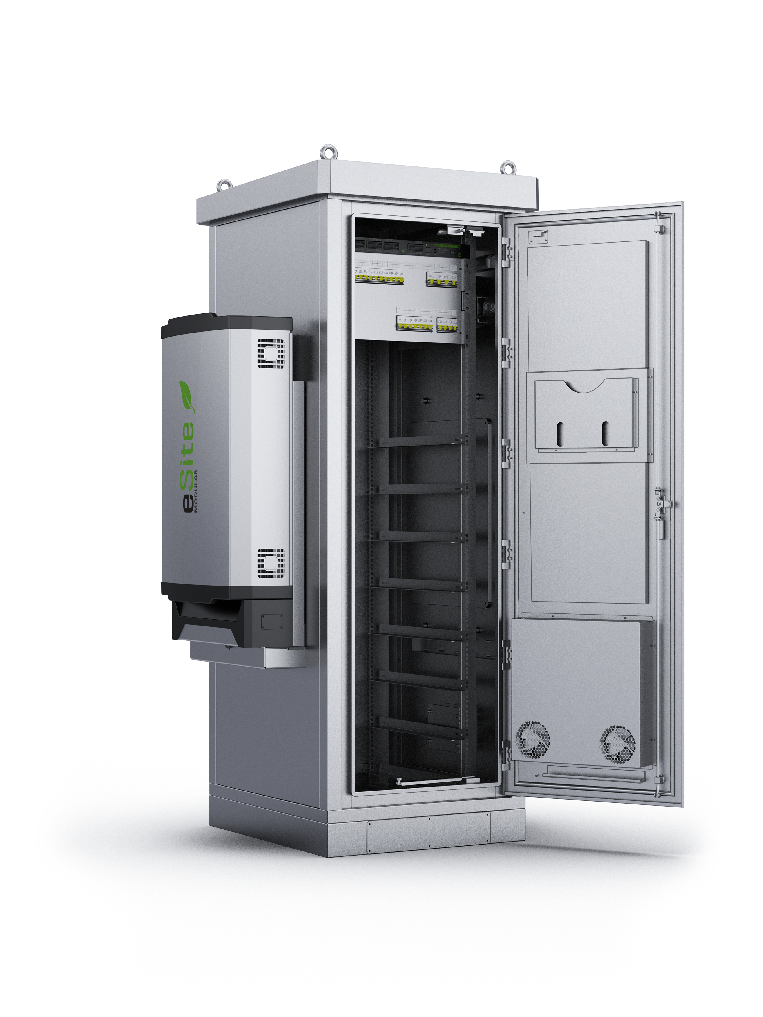
Figure 3.1. The eSite Modular system with Battery Cabinet, Converter Unit, Power Combiner Unit and Remote Monitoring and Control (RMC) unit.
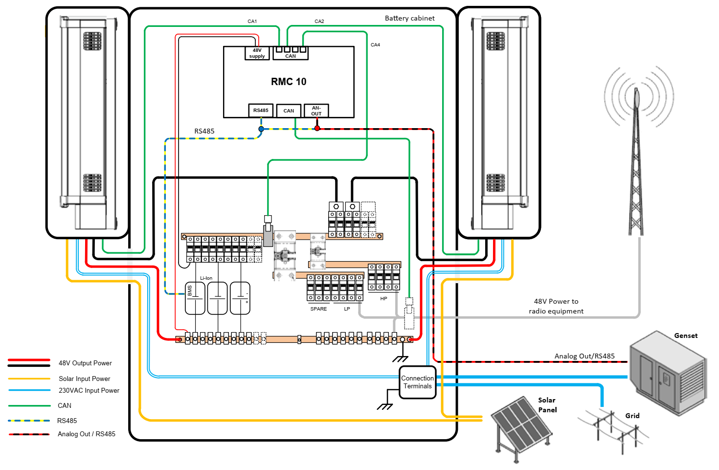
Figure 3.2. Line diagram of a complete setup of the eSite Modular system with power and communication connections to auxiliary systems.
3.2 Technical specifications
This section outlines the technical specifications of an example system with 1 RSE Converter Unit, equipped with 3 rectifiers and 3 solar converters.
| AC Input | |
|---|---|
| Nominal AC input | 230–250 V AC |
| Permitted AC input range | 85–300 V AC |
| Frequency | 45–65 Hz |
| Input current | 3 x 19 A |
| Power factor | >0.99 |
| THD | <5 % at 230 V AC, 100 % load |
| Input voltage derating | Linear derating for each phase, 3500 W @ 190 V AC, 1500 W @ 85 V |
| Protection | Varistor transient protection of all phases towards neutral. Varistor and GDT transient protection towards protective earth. Solid state transfer switch for long duration over voltages. |
| DC Output | |
|---|---|
| Operational range | -42 – -58 V DC |
| Rectifier capacity | 3 x 3500 W |
| Output power | 10500 W |
| Current | 195 A @ 54 V |
| Max current | 235 A |
Output Power derating by Ambient Temperature, | Continuous power at 45 ⁰C: 9750 W |
Output Power derating by Ambient Temperature, Cyclic Operation (230 VAC). | Full power at 45 ⁰C for 65 min, then derating to 9750 W |
| Rectifier peak efficiency | 95 %* |
| DC power system efficiency | 94 % |
| DC power port for Low Priority Load | 7000 W |
| DC power port for High Priority Load | 3000 W |
*The value includes an integrated static transfer switch.
| Solar Converter | |
|---|---|
| Nominal input voltage | 125 V DC |
| Permitted input voltage range | 50–150 V DC |
| Maximum input current | 3 x 20 A |
| Power conversion capacity | 6,6 kW |
| Power conversion peak efficiency | > 96.5 % |
| Environmental | |
|---|---|
| Nominal Temperature | - 20 – + 45 °C |
| Operating Temperature | - 20 – + 50 °C |
| Storage Temperature | - 40 – + 70 °C |
| Relative Humidity | 0–99 % |
| Cooling | Passive Convection Cooling |
| IP Code | Main Compartment IP65 |
| EMC | ETSI EN 300 386 V1.6.1 |
| Safety | IEC/EN 60950-1:2005+A1+A11+A12+A |
| Environmental standards | ETSI 300 019-1-2 Class 2.3 Public Transportation |
| MTBF | >350 000 h (@T ambient 25 °C) according to Siemens SN29500 |
| Communication ports | |
|---|---|
| I/O | 20 Digital inputs; 10 Digital outputs; 4 Analog inputs; 2 Analog outputs (all configurable) |
| External Bus | CAN; RS485; Ethernet |
| WLAN | Wi-Fi access point as service interface; SMA Connector |
| Radio modem | UMTS/HSPA: 850/900/1900/2100 MHz |
| Service port | Ethernet, USB, Wi-Fi |
| Isolation | 3.0 kV AC mains – Earth |
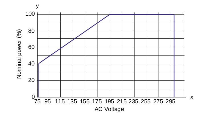
Figure 3.2. Power derating vs input voltage (@T < 45 °C)
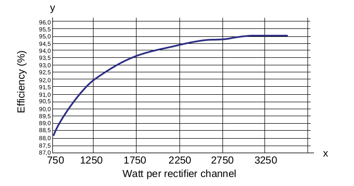
Figure 3.3. Rectifier efficiency vs converted power
Copyright © 2022 eSite Power Systems AB